The connection includes connecting the server to the switches which are connected to PLCs with a Cat5e Internet cable, and connecting I/O cards to field devices using 22 gauge wires, as indicated in Figure 8.
The DelatV system has primary and redundant networks.
Therefore, there are primary and secondary ports for two networks in the server. Accordingly, there are two switches for two networks.
Each of two PLCs is connected to two switches: primary port of PLC will be connected to the primary switch, and the secondary port of the PLC will be connected to secondary switch.
Figure 8 shows the wiring. The wiring from I/O cards to the field devices are connected through terminals in the DeltaV cabinet and DCS cabinet, as shown in Figure 8.
The wiring diagrams of each kind of I/O cards are explained below
All signals, their terminal numbers in DeltaV cabinet and DCS cabinet, their cable number, position in I/O cards, and their signal types are listed in the appendix A.
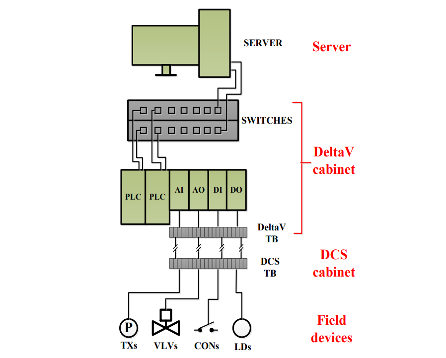
Figure 8 Schematic diagram of wiring system
The actual devices corresponding to the system indicated in Figure 8 are shown in Figure 9 to 12. Figure 9 indicates the server and the screen.
Figure 10 shows the DeltaV cabinet where all the PLCs, I/O cards, switches, DeltaV terminals and powers are mounted inside the cabinet. Figures 11 shows the DCS cabinet where all of the signals from the DeltaV cabinet are connected to the field devices.
Figure 12 shows all filed devices including control valves and transmitters.
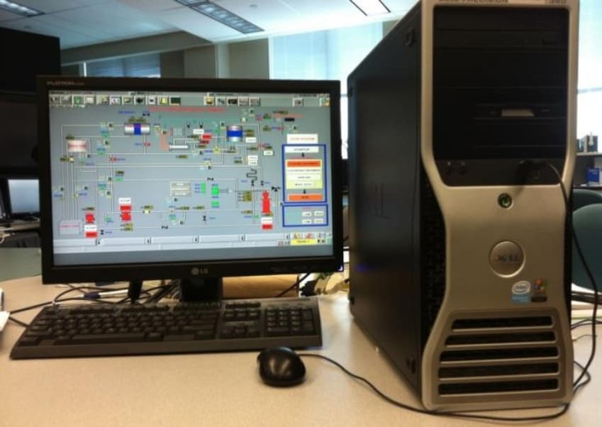
Figure 9 DeltaV server and screen
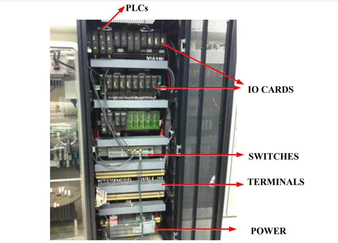
Figure 10 DeltaV cabinet
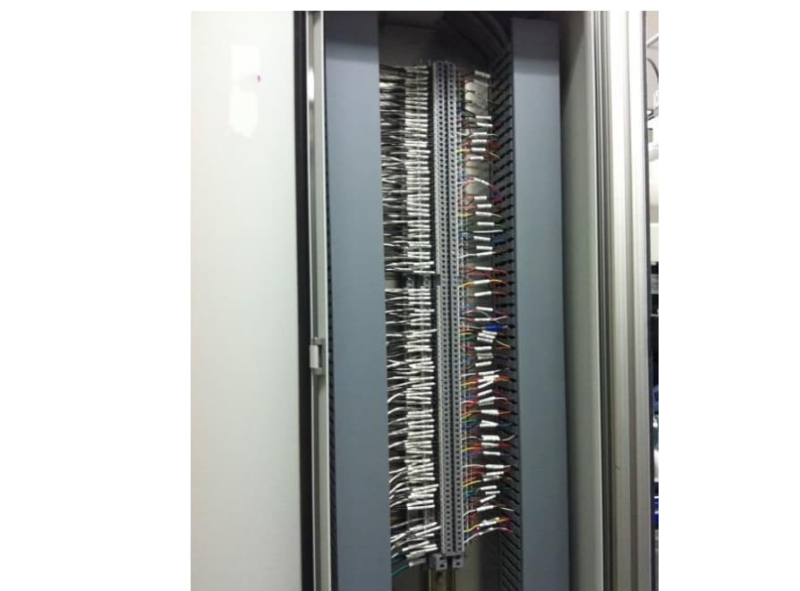
Figure 11 Wiring of DCS cabinet
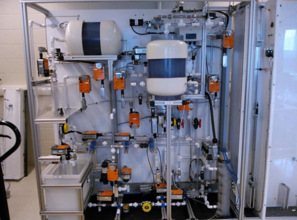
Figure 12 Field devices
Author: Ximing Liu