I/O cards communicate with CPU through carriers which hold all the I/O cards. Meanwhile, all the I/O cards need to be wired to the field devices in order to communicate with field devices.
AI card wiring
All the process variables, such as pressure, level, flow, temperature, are sent to the PLC in the format of 4-20 mA through analog input (AI) cards.
Because the 4-20 mA analog input signals have power source, 4-wire AI cards are used to isolate the power source in the AI cards to prevent the conflict of the two power sources in the AI signal circuit.
Wiring of the AI card is shown in Figure 3. Two wires of each signal from transmitter (“T”) are connected to the AI card termination (“+” and “-”), as shown in Figure 3.
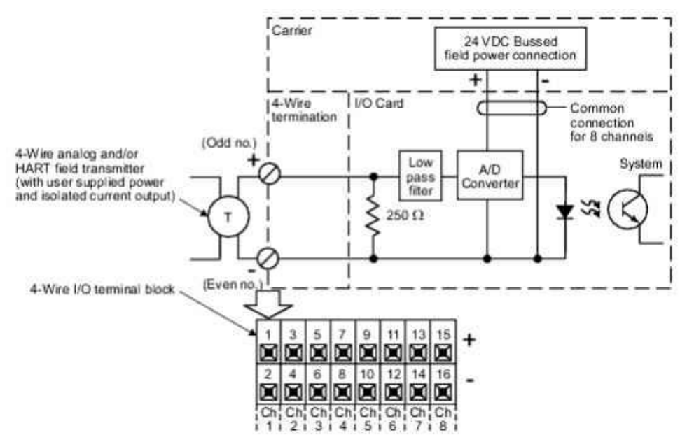
Figure 3 AI card wiring
AO card wiring
All the manipulated variables (AO), such as opening of valves and current of pumps, are in the format of 4-20 mA.
For analog output (AO) signals to activate the relays of valves or pumps, the power sources come from AO cards.
The two wires of each AO signals from field devices (“Load”) are directly wired to AO cards termination (“+” and “-”), as shown in Figure 4.
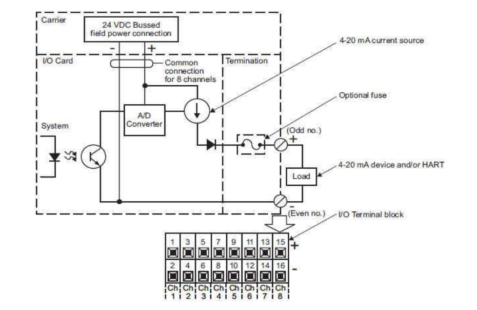
Figure 4 AO card wiring
DI card wiring diagram
Digital input (DI) signals indicate the switch status. The power source comes from DI cards.
The contacts of the switch are directly connected to the DI card termination (“+” and “-”), as shown in Figure 5.
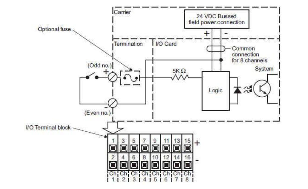
Figure 5 DI card wiring diagram
DO card wiring diagram
For digital output (DO) signals, DeltaV DO cards only allow DC power source. Therefore, except signals of “ROD DOWN”, “DOWN”, “INTERM”, and “HOME” which are powered by DC, other digital output signals which are powered by AC cannot be directly wired to DeltaV DO card and, thus, an intermediate circuit is needed.
Therefore, signals “ROD DOWN”, “DOWN”, “INTERM”, and “HOME”, are directly wired to DO card termination (“+” and “-”), as shown in Figure 6.
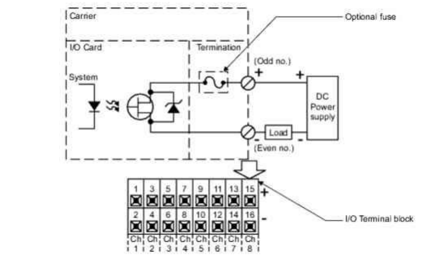
Figure 6 DO card wiring diagram
Others, shown as “Load” in Figure 7, are wired to the contacts of the relays (“RELAYS R_DO1_1~8” in Figure 7) in the intermediate circuit and the relays (“RELAYS R_DO1_1~8” in Figure 7) are wired to DO cards, as shown in Figure 7
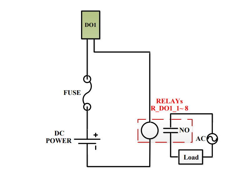
Figure 7 DO signal intermediate circuit
Author: Ximing Liu