Industrial control systems are always very complex and cumbersome to handle. For electronics engineers, it is becoming very essential to understand the computer control system using a programmable logic controller (PLC) and supervisory control and data acquisition (SCADA) system.
Here is a very efficient and expandable robust control system solution for industrial purposes. For the proposed system, we have used AB Allen Bradley MicroLogix 1400 PLC 1766, Wonderware InTouch 2012R2 SCADA system and KEPServer version 5 software for communicating between the PLC and SCADA. Wonderware InTouch SCADA is becoming increasingly popular due to its powerful user-friendly graphics as shown in Fig. 1.
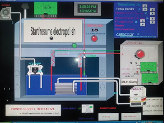
Fig. 1: A typical Wonderware InTouch graphical user interface
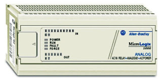
Fig. 2: MicroLogix 1000 PLC (Model 1761-L10BWA features 120V/240V AC power, six 24V DC digital inputs and four relay outputs)
- The RSLogix family of IEC-1131-compliant Ladder logic programming packages help you maximise performance, save project development time and improve productivity. This family of products has been developed to operate on Microsoft Windows operating systems. Supporting Allen Bradley SLC 500 and MicroLogix families of processors, RSLogix 500 was the first PLC programming software to offer unbeatable productivity with an industry-leading user interface. PLC is programmed using Ladder programming in RSLogix software. Different inputs and outputs have different addresses. Mostly the field devices, which are to be controlled, are connected to the PLC via digital input, analogue input, digital output and RS232, among others. The address of each device, module and register is specific to each PLC manufacturer, including Allen Bradley, Siemens, Schneider, Mitsubishi, Hitachi and Delta.
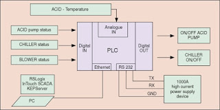
Fig. 5: Schematic diagram for PLC connections
-
The PLC is connected to the PC via the Ethernet. Since both PLC and SCADA are from different manufacturers, we used an intermediate OPC link (communicator) between these. This job is done by
KEPServer, which is installed on the PC. -
The PLC IP address is configured using software tool BOOTPServer.
-
When the main SCADA is running, applications like KEPServer should be running in the background and PLC should be in online mode.
-
Using SCADA, a graphical user interface (GUI) is built to monitor and control various parameters like current/voltage and to switch on/off various devices.
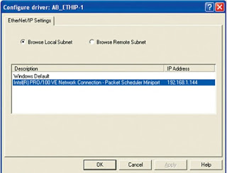
Fig. 6: Interfacing the PLC via the Ethernet to a PC to make it available to software for configuration and programming
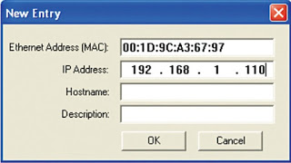
Fig. 7: Setting BOOTP server properties
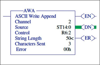
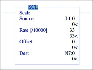
Fig. 10: SCL instruction set
For a beginner, it is better to start with the MicroLogix family of PLCs from Allen Bradley. MicroLogix 1000 controller offers control capabilities in an affordable, compact package. MicroLogix 1200 provides features and options to handle an extensive range of applications. The expandable MicroLogix 1500 controller helps you achieve high-level control in a variety of applications. MicroLogix 1100 and MicroLogix 1400 controllers increase application coverage with enhanced network communications at affordable prices. RSLogix 500 programming software and RSLogix Micro programming software provide an instruction set that is common to MicroLogix and SLC 500 controller families.
MicroLogix 1000 PLC system. MicroLogix 1000 PLC (Fig. 2) is available in 10-point, 16-point or 32-point digital input/output (I/O) versions. Analogue versions available with 20 digital I/O points, four analogue inputs (two voltage and two current) and one analogue output (configurable for either voltage or current) provides a compact form factor, with footprints as small as 120mm x 80mm x 40mm (4.72 x 3.15 x 1.57 inches).
It offers fast processing with typical throughput time of 1.5ms for a 500-instructions program and has a pre-configured 1kB program and data memory to ease configuration. It includes built-in EEPROM memory; hence, there is no need for battery back-up or a separate memory module.
The device offers peer-to-peer messaging (up to 32 controllers on a DH-485 network) through a 1761-NET-AIC communication interface. Communication takes place via DeviceNet and EtherNet/IP through 1761-NET-DNI and 1761-NET-ENI communication interfaces.
It also includes a built-in high-speed counter (only on controllers with 24V DC inputs) and lets you customise input response times and noise rejection using adjustable DC input filters.
The device supports simple connectivity through an RS232 communication channel to a PC for program upload, download and monitoring.
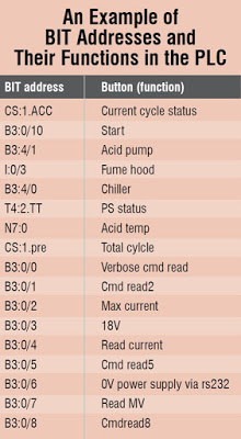
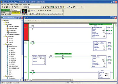
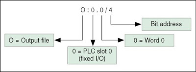
Fig. 12: A typical address for AB PLC
MicroLogix 1400 PLC system. The 1766 MicroLogix 1400 PLC system (Fig. 3) is built upon critical MicroLogix 1100 features, including EtherNet/IP, online editing and a built-in LCD panel. These controllers feature a higher I/O count, faster high-speed counters, pulse train output, enhanced network capabilities and a backlight on the LCD panel. Controllers without embedded analogue I/O points provide 32 digital I/O points, while analogue versions offer 32 digital I/O points and six analogue I/O points. You can expand all versions with up to seven 1762 expansion I/O modules.
The Ethernet port provides Web server capability, email capability and protocol support for DNP3 protocol support. The built-in LCD with a backlight lets you view the controller and I/O status. It also provides a simple interface for messages, bit/integer monitoring and manipulation.
Application capabilities can be expanded through support for up to seven 1762 MicroLogix Expansion I/O modules with 256 discrete I/Os, up to six embedded 100kHz high-speed counters (only on controllers with DC inputs), two serial ports with DF1, DH-485, Modbus RTU, DNP3 and ASCII protocol support.
There are 10kB words in the user program memory with 10kB words in the user data memory, and up to 128kB for data logging and 64kB for recipe.
PLC connections
One can buy a compact AB Allen Bradley MicroLogix 1400 PLC 1766, with eight DIO and two built-in serial ports (model 1766) for initial development. We used MicroLogix 1400 controllers, which are suitable for use in an industrial environment. Specifically, this equipment is intended for use in clean, dry environments.
Typical PLC connections for automation of an experimental facility are shown in Fig. 5. Allen Bradley Micro Logix 1400 has various digital input and digital output pins operated by +24V DC. An analogue input module is added separately. Another high-current 1000A power supply device is connected via RS232 protocol, where only three lines, namely, TX, RX and GND, are used for communication via a PLC serial port. Finally, AB PLC is connected to the PC via an Ethernet port.
RS232. RS232 is a serial protocol that converts parallel data to serial bits (pulses) and sends these across three wires, that is, TX, RX and GND. In most cases, the number of wires required is just three, but in special circumstances it may go up to nine wires, say, an RS232 modem.
Allen Bradley 1400 series has two serial ports. The first one is through a PPI cable with a 9-pin D connector at the other end. This needs a NULL modem connector to connect to any PC having a serial port or USB serial adaptor. NULL modem connections are shown in Fig. 4.
Interfacing the PLC to a computer. MAX1400 has three ports. First is COM1 (round connector); second is COM2 (9-pin D connector), which is for RS485/RS232 communications; and the third is Ethernet for Ethernet/IP driver based communications. Therefore it is pretty easy for anyone to configure Ethernet as download port and COM1 as serial port for RS232 communications.
Allen Bradley PLC is connected to the computer via the Ethernet. We need to interface the programmable controller in order to configure and program (Fig. 6).
Adding drivers. Adding a driver is required for RSLOGIX classic software. To do so, you need to click on the middle icon and add RS232 DF1 driver to it.
Software for interfacing. RSLinx Classic is a software tool from Rockwell Automation Networks and Devices. It is a comprehensive factory communication solution, providing Allen Bradley PLC access to a wide variety of Rockwell Software and Allen Bradley applications, ranging from device programming and configuration applications such as RSLogix.
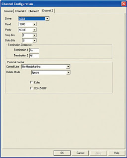
fig. 13: Setting RS232 channel configuration
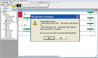
Fig. 14: Downloading the Ladder program to the PLC
BOOTP server is a suitable server to establish communication between PC and Rockwell PLC.
Communicating to hyper terminal. How does one know that the PLC is transmitting characters out of its serial port? You can view the pulses or protocol produced using a hyper terminal window.
For that, you need to set the hyper terminal settings to 19200, N, 8, 1, which is same as the settings of PLC serial DF1 driver.
Double-click MAC and enter the IP (Fig. 7).
Ladder programming. Once the AB PLC is successfully interfaced to the PC, we need to properly program it using RSLOGIX provided by Rockwell Automation. For programming the PLC, we use Ladder programming. Typical PLC programs use blocks like timers on and off, counters, digital I/Os, RS232 communication blocks and others.
Ladder program is similar to the wiring diagram of the circuit. We redraw the wiring diagram using two vertical lines to represent input power rails and stringing the rest of the circuit between these. Sub-routines are implemented as another ladder.
A typical example of a block used for RS232 programming is AWA (Fig. 9).
ASCII write append (AWA). The AWA instruction sends a specified number of characters (for example, 50) of the source tag (ST14:0) to a PLC serial port 2 and appends either one or two pre-defined characters. It is used for RS232 communication.
Similarly, an SCL is an instruction used to read and scale an analogue input to a corresponding physical value like temperature or pressure.
In the above example, the address for the analogue input is I: 1.0 and the converted raw data is divided by 10,000 and added to offset to implement a linear transfer function like
y = mx + c
A number of free Ladder programming tutorials are available on the Internet. Inside the PLC, we have various registers like output, input, status and binary. Each bit in these registers specifies a function. Addresses of the devices are built on the basis of names, PLC slot numbers, words and bit numbers. Address representations differ from manufacturer to manufacturer.
The table above shows some of the bit addresses of the PLC and how these are related to field devices.
A typical address of an AB PLC for output coil is built as in Fig. 12.
Once you write your Ladder code for the PLC, download the code into the PLC. Let the PLC be in Run mode after that.
Fig. 13 shows how an RS232 port can be configured for handshaking a power supply device, which has settings 9600, N, 8, 1.
Wonderware InTouch SCADA
Wonderware’s InTouch HMI software for visualisation and industrial process control offers outstanding ease of use and simple-to-configure graphics. For having an interactive GUI to control outputs of PLC, RS232 devices via PLC, we use Wonderware InTouch SCADA. A simple GUI can be made in Wonderware by following simple steps:
- Open Wonderware Development tool by double-clicking on Desktop icon.
- Start a new project.
- From the palette on the right side, choose the appropriate graphical object to be inserted.
- Click on the screen to insert the object.
- Double-click on the object to add a suitable tag name and type of object. Type defines usage; it may be analogue or discrete.
- Double-click on the tag to assign properties to the object. Different operations like visibility or blink can be controlled on the basis of scripting.
- If the tag is I/O type (meant to read or control a device), specify the address of the device.
- Address of the device can be obtained from registers of the PLC, which can be viewed in RSLogix.
- In Modify Access Name window, keep the access name as KEPServerEX_SL. KEPServer acts as a communicator between RSLogix and Wonderware InTouch.
- In this fashion, develop the entire GUI with specific tag names, addresses of devices and PLC variables used in Ladder logic.
Access name. Each PLC uses a specific protocol to communicate with the I/O server or DA server. InTouch then uses an access name concept to continue this communication for dynamic data exchange (DDE). Typically, because here KEPServer is acting as a communicator between PLC RSLogix and Wonderware InTouch, we specify access name in InTouch as KEPServerEX_SL. Access names are selected in the tag name dictionary for each tag used in the application.
Scripting. In all control systems, it is essential to provide software interlocks to prevent human errors. So the best method would be using Window Scripts in InTouch. Window scripts execute periodically when an InTouch window is opened, or one time when an InTouch window is opened or closed.
Programming here is done using scripts, which is similar to any programming language. A typical scripting example is shown in Fig. 18.
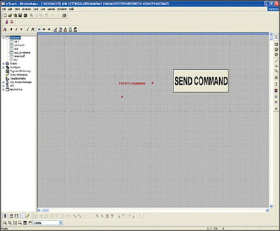
Fig. 16: Wonderware development tool
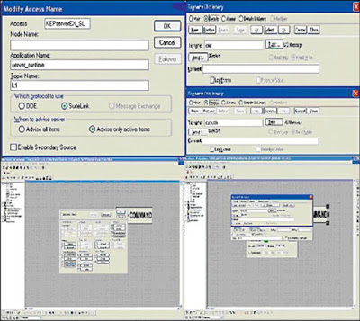
Fig. 17: Setting tag properties
KEPServer
KEPware’s OPC server KEPServerEX provides an easy and reliable way to connect the Allen Bradley PLC to HMI, SCADA, Historian, MES, ERP and countless custom applications. Here, you can use KEPServer for communicating RSLOGIX to Wonderware InTouch using the Ethernet/IP protocol.
Be careful while specifying tagnames in KEPServer. Tag names and their corresponding addresses should match those mentioned in Wonderware InTouch development.
Running the final application
Once your PLC code is downloaded into the PLC and run from RSLogix, run KEPServer. Open the runtime application of Wonderware InTouch software and open your GUI file. Always make sure that KEPSersver is running in the background while you run Wonderware InTouch application.
Applications
Such a control system can be very useful for industrial automation, in research laboratories and big industries. The graphical interface makes it easy for the operator to operate switching and controlling operations. The PLC provides a very rugged solution to control relays and RS232 devices.
Author - Arvind soni