A counter is a simple device used for counting. There are different types of counters. There are up-counters (that only count up 1, 2, 3 …). These are called CTU (Count up), ‘CM’, C or CTR. There are down counters (that only :count downwards, that is, reversed 9, 8, 7). These are typically called CTD ‘(Count down). There are also up-down counters (they count up and/or down). These are typically called UDC (up-down counter).
Most manufacturers also include a limited number of high speed counters. These are commonly called HSC (High Speed Counter), CTH (Counter High Speed). Typically a high speed counter is a hardware device. The normal counters listed above are software counters. In other words, they do not physically exist in the PLC but rather they are simulated in software. Hardware counters do exist in the PLC and are not dependant on scan time.
As a rule, it is important to use the normal (software) counters unless the pulses you are counting arrive faster than twice the scan time, e.g. If the scan time is 2 ms, and pulses arrive for counting every 4 ms or longer, then use a software counter. If they arrive faster than every 4 ms (3 ms, for example) then use the hardware (high speed) counters. To use the counter the following should be known.
The source of the pulse to be counted typically, this is from one of the inputs, i.e. a sensor connected to input 0000.
How many pulse to be counted before activation. For example, let us say 5 objects are to be counted.
When/how the counter will be reset so that it can count again. For example, let us say after 5 objects let us reset the counter.
When the program is running on the PLC, the program typically displays the current or accumulated value so that we can see the current count value.
Typically counters can count from 0 — 9999, — 32,768 to +32,767 or 0 —65535, since most PLCs have a 16 bit counters. 0 — 9999 is a 16 bitBCD and —32768 — + 32767 and 0 — 65535 are 16 bit Binary.
Figure. 21.43 shows a counter with 2 inputs. One goes to the reset line and when this Input in turned on, the current (accumulated) count value will return to zero. The second input in the address from where the pulses arrive that are used for counting. Let us consider an example. If we are counting the number of objects that pass in front of the sensor that is physically connected to input. 0001, then normally open contacts with the address 0001 would be connected in front of the pulse line.
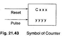
In Fig. 21.43 Cxxx is the name of the counter. If the counter is called 000 then C000 would be written.
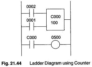
YYYY is the number of pulses that is used for counting. If 10 objects are to be counted before turning on a physical output to box these, then 10 would be placed. If 100 is to be counted then 100 would be placed here. When the counter has finished counting YYYY objects, it will turn on a separate set of contacts that are also labelled Cxxx. It is important to note that the counter accumulated value only changes at the off to on transition of the input pulse. Figure. 21.44 shows, the Symbol Counter on a ladder and how the counter can be set up. Let the counter be called C000 to count 100 objects from 0001 input before turning on output 0500. Sensor 0002 resets the counter.
Different types of counters are used for up counting, down counting or up-down counting. The Symbol Counter for an up-down counter (UDC) is shown Fig. 21.45. Let us name it UDCxxx and yyyy as before.
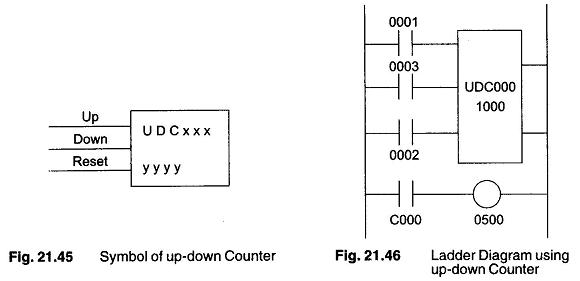
A UDC needs three inputs. The reset input has the same function as described earlier. However, now instead of having only one input for pulse counting, two inputs are used for counting. One pulse input is for counting up and the other is for counting down. Let us consider an example in which the counter is named UDC000 and give a preset value of 1000, i.e. it will count 1000 total pulses. For inputs, sensor are used, one of which turns, input 0001 on when it sees a target and another sensor at 0003 also turns on when it sees the target. When input 0001 turns on, the counter counts up and when input 0003 turns on, the counter counts down. When 1000 pulses is reached the output 0500 will be turned ON. The ladder is as shown in Fig. 21.46.
In most PLCs, it is important to note that counters and timers cannot have the same name.