The circuit in figure is for
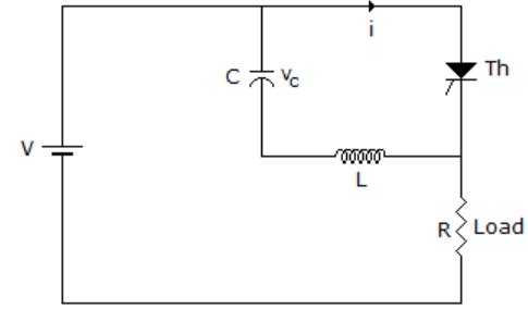
A. resonant commutation
B. self commutation
C. load commutation
D. auxiliary commutation
Show Answer
Answer: B
Share your understanding of this question with the correct explanation.
The circuit in figure is for
A. resonant commutation
B. self commutation
C. load commutation
D. auxiliary commutation
Answer: B
Share your understanding of this question with the correct explanation.