General Information
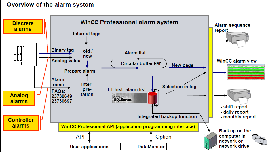
With the alarm system, events from the controller or from the monitoring function in WinCC (operating states, faults, user input etc.) Are displayed in the form of alarms, logged if necessary and reported and acknowledgements by the operator are accepted. To allow this, alarms need to be configured in alarm classes. To allow the history to be followed as well, the alarms are stored on the hard disk in a long-term historical alarm list on the local computer. The alarm system of WinCC Professional is based on the directions of DIN 19235. The alarm system of WinCC Professional provides discrete, analog, user and controller alarms
Alarm types in WinCC
WinCC supports the following alarm types:
User-defined alarms
- Analog alarms
Analog alarms are used to monitor limit violations. - Discrete alarms
Discrete alarms are used to monitor states.
System-defined alarms
- System events
System events belong to the HMI device and are imported into the project. System events monitor the HMI device.
Message blocks
Minimize downtimes – by means of alarms and messages
SIMATIC WinCC records process signals and local events, saves them in archives and makes them available filtered or sorted, as needed. Messages can occur via the derivation of the individual bits of a Power Tag (max. 32), as a result of a chronological message frame directly from the automation system, as a result of analog alarms due to any number of limit value violations, or due to an operation (operation message). Each message can be configured in such a way that the operator has to acknowledge it. Now it is also possible to compare tags with a defined value. In doing so, hysteresis values can be set and ranges can be monitored easily.
User-definable message structure
Because the message structure is freely definable, it can be tailored to the special requirements of your plant. Dividing the structure into as many as 10 different text blocks (plant ID, fault location, text, etc.) Leads to greater clarity of the information and allows targeted analyses to be initiated in connection with the filtering or sorting function. Differentiation of as many as 16 message classes makes easy fault and status messages just as possible as the separate preparation of alarms, warnings, faults and errors for several areas of the plant. Within a message class (e.g. Alarm), up to 16 priorities can also be differentiated.
User-friendly message view
Messages are displayed on the screen via the user-configurable WinCC Alarm Control. Here, the display of the message information, for example, can be adapted exactly to the needs of the operator. The settings made can be saved in user-specific or global templates. WinCC Alarm Control for displaying current/historical messages Based on the contents of the individual message blocks, filtering, selecting and sorting is possible in the screen, e.g. Chronologically, according to priorities or fault location. The contents can then be exported directly as a CSV file or printed as a report. A freely definable toolbar function also provides a high degree of flexibility. In this way, for example, your own project-specific functions can be integrated. To maintain a clear overview of a large number of incoming messages, the operator can suppress unimportant operational messages on the screen display by means of Alarm Hiding. The messages continue to be archived in the background.
Archiving and logging messages
The Microsoft SQL Server is used for archiving message. This ensures complete recording of all events. Messages are archived in the case of so-called message events, for example, when a message occurs and when the status of the message changes. In the message sequence report, the messages can be (selectively) documented chronologically. All of the status changes (came in, went out, acknowledged) of all currently pending messages are output to a printer. In the message archive report, specific views of the archived messages can be generated.
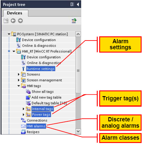
Steps in configuring an alarm
Below is the procedure to configure the alarm in WinCC.
- Configure alarm blocks
- System blocks
System blocks are system data, for example date, time, alarm number and status. - User text blocks
User text blocks contain the alarm text with the description of the cause of a fault and additional texts with information, for example the location to help localize the fault. - Parameter blocks
Parameter blocks are used to link the alarms to process values, for example, current fill levels, temperatures or speeds. Up to 10 parameter blocks can be configured per alarm.
- Set alarm classes
- Configure your own alarm classes.
- Specify alarm settings
- Display suppression.
- Back transfer of alarms.
- Configure trigger tags
- Bit string for discrete alarms.
- Threshold tags for analog alarms.
- Configure discrete alarms
- Configure analog alarms/ discreet alarm.
Procedure for Configure discrete alarms
- Select HMI alarms in project tree.
- Choose discrete alarm
- Assign ID (i.e. 1, 2, 3, .etc.)
- Alarm text Write text that you want display on alarm screen when it will be executed (example “tank limit exceed!”).
- Alarm classes : define class of alarm (i.e. Error, acknowledge, warning)
- Trigger tag: Assign HMI tag that you have chosen for HMI alarms (first you have to create HMI tag Assign HMI tag’s memory bit that can be used as Triggering Bit to triggered the alarm.
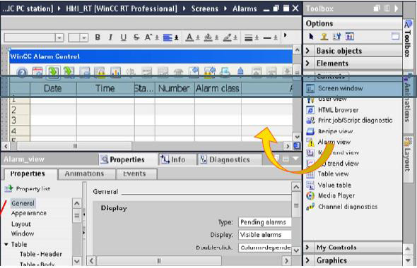
- Take Alarm View from Toolbox > control. (you can also set appearance for Alarm view)
- Compile and test your program in Runtime.
Displaying alarms
So as not to overload the plant operator with information, the display of alarms can be suppressed automatically or manually. If alarms are suppressed (hidden), they are logged but not displayed.
There are two ways of suppressing the display of incoming alarms:
Automatic suppression of the display
The alarms are not displayed depending on a certain system status. To do this, alarm suppression must be configured for certain plant statuses, for example plant startup or plant shutdown.
Manual suppression of the display
The user suppresses the display of an alarm in runtime when necessary using the "Hide alarm “button in the alarm view. When necessary, the user can display the alarm again using the “Show alarms” button.
Alarm View properties
The settings for the position, geometry, style, color and font of the object are made in the Inspector window. The following settings need to be selected for an alarm list display.
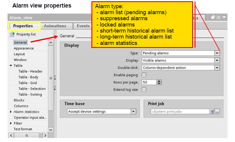
General/Display:
Type:
Pending alarms
Display:
All alarms
Double-click:
E.g. Loop-in alarm: Specifies that double - clicking on an alarm, triggers a configured screen change.
General/Time base:
Accept device settings. Here, you specify the time base with the alarms are output.
Appearance:
Set the appearance for Alarm view.
Layout:
Here, the position and size of the alarm view is defined.
Window:
Settings title: e.g. “Blast furnace-W”
Table:
Activate display of the column and row headers. Specifies the properties (color, column labeling, and row numbers) of the table in the alarm view.
Blocks:
Adopt project settings with these settings, the blocks created in the alarm configuration are selected for further use in the column configuration.
Columns:
Specifies the columns of the table in the alarm view. Each column corresponds to an alarm text block. Here all available alarm text blocks should be selected. Here, only the alarm text blocks selected under “Blocks” are displayed.
Toolbar:
At least the following buttons should be available in the taskbar: Alarm list, short and long-term archive, acknowledgment (single/group acknowledgment), selection dialog (filter), and auto scrolling and for navigation in the alarm lists: First alarm, next alarm, previous alarm, latest alarm
Status bar:
Specifies the elements of the status bar. In runtime mode, these elements show, for example, information about the number of pending alarms.
Additional functionality with WinCC Runtime Professional
Alarms can occur via the derivation of the individual bits of a Power Tag (max. 32), as a result of a chronological message frame directly from the automation system, as a result of analog alarms due to any number of limit value violations, or due to an operation. In doing so, hysteresis values can be set and ranges can be monitored easily. Since the alarm structure is freely definable, it can be tailored to the special requirements of a plant. Dividing the structure into as many as 10 different text blocks (plant ID, fault location, text, etc.) Leads to greater clarity of the information and allows targeted analyses to be initiated in connection with the filtering or sorting function. Differentiation of as many as 16 alarm classes permits the separate preparation of alarms, warnings, faults and errors for several areas of the plant. Within an alarm class (e.g. Warning), up to 16 priorities can also be differentiated.
Based on the contents of the individual alarm blocks, filtering, selecting and sorting is possible in the screen, e.g. chronologically, according to priorities or fault location. Then the contents can be exported directly as a CSV file or printed out as are port. A freely definable toolbar function also provides a high degree of flexibility. In this way, for example, your own project-specific functions can be integrated. To maintain a clear over view in the event of a large number of incoming alarms, the operator can suppress unimportant operational messages on the screen display (Alarm Hiding). The alarms continue to be logged in the back ground. The Microsoft SQL Server is used for logging of alarms. This ensures gap-free recording of allevents. Alarms are logged when alarm events occur. In the alarm sequence report, the alarms can be (selectively) chronologically documented. In the alarm log report, specific views of the logged alarms can be generated.
Reporting and logging system
The integrated WinCC report system prints data acquired during the runtime in configurable and page-based layouts by means of various types of reports, ranging from alarm sequence reports, system alarm and operator input reports, to user reports. Of course, these logs can also be configured in multiple languages. The report output can also be started time-controlled or event-driven or by operator input. The printer can be selected online via a printer selection dialog. The contents of a report can be determined dynamically during runtime. WinCC reports can contain data from the database and external data in CSV format as a table or trend. Data from other applications can be integrated as tables or graphics via customer- Specifically developed Report Providers