Butterfly Valves
A butterfly valve is composed of two semicircular plates hinged on a common spindle, used to permit flow in one direction only. Butterfly valves are of the quarter-turn family and are so designed because a 90-degree turn of the operator fully opens or closes the valve.
The valve uses elastomer seats and seals and their surge in popularity can be attributed to these advantages. In some cases, they may be used for non-critical throttling applications. They are lighter in weight than conventional valves. The position of the lever indicates whether they are wide open, partially open, or fully closed.
Butterfly valves are compact and space-saving and easily installed in new piping or as replacements in existing piping. They are easily adapted to lever, manual, gear, electric, or pneumatic operation.
Gate Valves
Gate valves are, by far, the most widely used in industrial piping. They are used as stop valves – to fully shut off or fully turn on flow – the only job for which gate valves are recommended’’’.
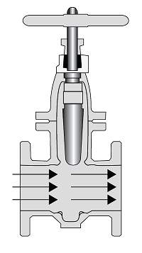
Gate valves are inherently suited for full open service. Flow moves in a straight line and practically without resistance when the wedge is fully raised. There are two basic designs of gate valves: inside screw stem and outside screw stem.
Seating is perpendicular or at right angles to the line of flow – meets it head on. That is one reason why gate valves are impractical for throttling service. When throttling is necessary, globe valves should be used. Repeated movement of the wedge near the point of closure, under high velocity flow, may create a drag on the seating surfaces and cause galling or scoring on the downstream side. A slightly opened wedge may also cause turbulent flow with vibration and chattering of the wedge.
A gate valve usually requires more turns to open it fully. Also, unlike many globe valves, the volume of flow through the valve is not in direct relation to the number of turns of the hand-wheel.
Globe Valves
Unlike the perpendicular seating in gate valves, globe valve seating is parallel to the line of flow.
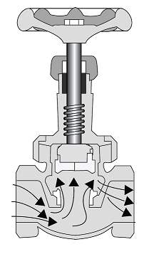
All contact between seat and disc ends when flow begins. These are advantages for more efficient throttling of flow, with minimum wire drawing and seat erosion. Valve disks and seats in most globe valves can be conventionally repaired or replaced – often without removing the valve body from the line.
Shorter disk travel, with fewer turns required to operate globe valves, saves considerable time and work, also wear on valve parts.
Check Valves
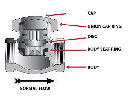
Check valves are designed to automatically prevent the reversal of flow in a pipeline system. They control the direction of flow, rather than throttling or isolating flow as other valve designs do. Reverse flow may create problems or it could cause damage to equipment. Check valves are sometimes known as ‘‘reflux’’ valves.
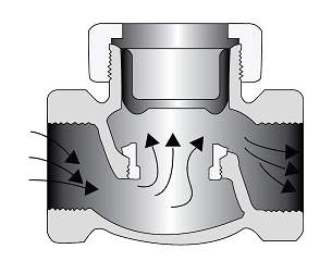
There are several basic designs of check valves, a few of which are described below.
Swing Check Valves
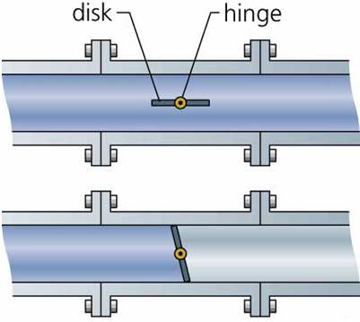
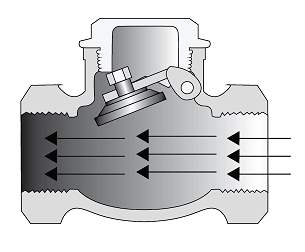
This type of check valve uses a hinged mounted disc that swings open and closed with flow. They can be used in the horizontal and vertical (flow upwards) position. The swing check is the most commonly used design of check valve as it does not restrict flow.
Lift or Piston Check Valve
This type of check valve uses a piston rather than a hinge-mounted disc to prevent the reversal of flow. This provides a cushioning effect during the operation of the valve. They must only be used in a horizontal position. Lift check valves, like globe valves, are flow restricting; therefore, they are generally used as companions to globe valves.
Pressure Relief Valves
‘‘Pressure relief’’ is simply a dumping of excess fluid safely into the atmosphere. The excess fluid is that which would cause pressure to exceed the safety limit. The relief/safety valve is the most widely used piece of equipment in this category. However, liquid seals and rupture discs may also be used.
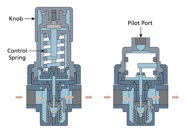
There are two basic kinds of relief valves: self-operated and pilot-operated. The spring-type relief valve is the most widely used. The pilot-operated type is also frequently used, and it offers more precise operation. The pilot-operated type is more frequently used as pressures become higher and capacities greater.
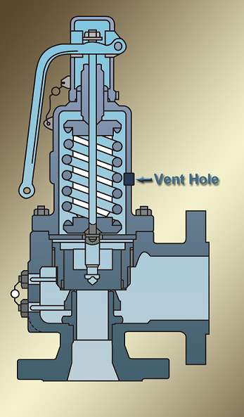
Pressure relief valves are designed to open automatically at a pre-determined set pressure level of system pressure and to achieve a rated relieving capacity at a specified pressure and temperature above the set-point (over-pressure) before re-closing at a pressure below the opening point (blowdown). The simplest and most reliable type of pressure relief valve, even some four-hundred years on from the first design, is the spring-loaded design where a spring force opposes the system pressure acting on the valve disc. When the system pressure rises above the level of the spring force, the valve opens. This valve type may also be fitted with a bellows for better emission control performance.
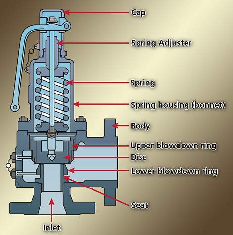
The significant elements of all spring-loaded pressure relief designs are the springs and the seats. The springs must provide the desired compression rate and a reasonable range of adjustment. They must also fit into the valve bonnet and stay within the design perimeters. The seats may be flat or angled, metal or soft. As the seat area usually defines the load transmitted to and from the spring, very high precision is essential to ensure proper valve operation.
A second type of valve, which is more sophisticated and offers operating advantages in selected applications, is the pilot-operated pressure relief valve.
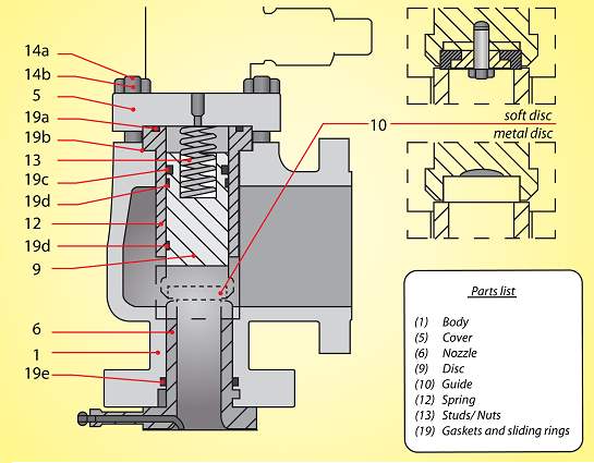
This type of valve consists of a main valve and a pilot valve. The pilot responds directly to system pressure and communicates with the main valve. As with the spring-loaded valve, many unique models exist. However, some common design features of pilot-operated pressure relief valves include the sensing line, pilot valve, and main valve.
The sensing line is either connected to the valve inlet or a remote location and conveys system pressure to the pilot.
The pilot valves senses and responds to the system pressure. The pilot is the controlling member of the valve system and determines all of the operating characteristics of the valve. It consists of many small parts and passages and usually relies on elastomer seals for operation.
The main valve operates in response to the pilot and provides the main rated flow capacity to reduce excess pressure.
Regulating Valves
Regulating valves are used in many systems on a boiler from feed flow to fuel flow. Regulators attempt to manage flow by adjusting the flow area available to the fluid. Most designs incorporate a plug or similar element that occupies a portion of a stationary orifice while throttling. In an action often called ‘‘modulation’’, the plug or similar element is shifted to increase or decrease available flow area. Flow through a particular size of open orifice area is primarily dependent upon the available pressure difference.
Where the managed parameter is pressure, obviously, flow and pressure are interdependent. While the pressure being maintained may be at a location remote from the valve, there must always be an immediate and inherent relationship maintained among the managed flow, the pressure to which the regulator is responding and the regulator’s response mode. Essentially, the regulator must be able to influence pressure at the measured point and must exercise that influence in the appropriate direction of response.
Where the managed pressure is upstream from the regulating valve, you normally would want the valve to open to permit flow as pressure begins to rise.
Therefore, the valve’s response disposition is “open on rise.” The term normally applied to this mode of operation is inlet pressure regulator function. Conversely, if managed pressure is downstream from the valve, the valve’s disposition would be “open on drop,” and the normal reference for function is outlet pressure regulator.
Finally, regulators often are called upon to manage operating conditions other than pressure, such as temperature or flow. A regulator will be either direct- or pilot-operated. Direct-operated regulators are simple, single-minded devices intended for a specific application within a particular range of pressures.
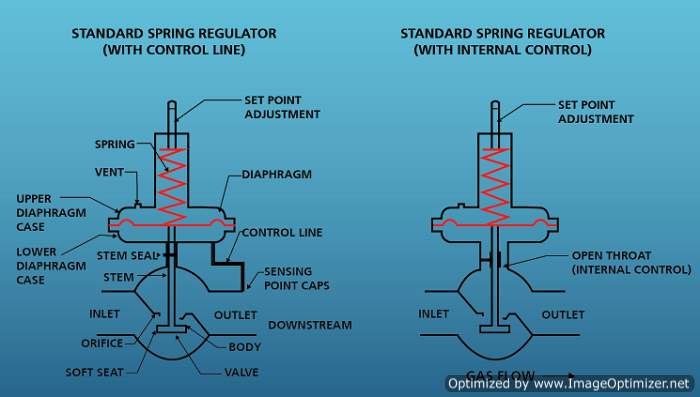
Direct-Operated Regulator
In a direct-operated pressure regulator, managed pressure is applied to some internal surface within the valve. The resulting force is transmitted to the modulating parts of the valve and balanced by a second force applied within the valve. In many cases, the second force is adjustable to establish the set-point. Movement of the modulating parts inherently involves a change in the balanced forces and thus a change in the managed pressure. The more the demanded flow deviates from what the regulator was experiencing at the time it was first adjusted, the more the pressure must deviate from set-point.
Pilot-Operated Regulator
A pilot-operated regulator consists of a pilot section and a slave section. Two flows are managed by the valve. The first, which is by far the greater proportion of the total flow, is managed by the plug and orifice in the slave section. The second, the pilot stream, is managed by the pilot section. The pilot section may have its inlet connected to the immediate upstream side of the main valve or may source its flow from a higher pressure space. The pilot section’s modulating portion is available in all dispositions and functions of direct-operating regulators.
