Basics of Control loop in P&ID

The ‘Control loops’ used in a process industry in terms of a combination of two or more instruments or control functions arranged so that signals pass from one to another for the purpose of measurement and/or control of a process variable.

The goal of process control instrumentation is to measure, monitor, and or control a process.

Basics of Control loop in P&ID

Following three tasks is associated with a control loop.

  • Measurement
  • Comparison
  • Adjustment

Before we proceed it’s very essential to have a basic concept on the following terms which are needed to understand a control loop in P&ID:

  1. [Instrument and controller symbol and identification letter.]
  2. [Different type of function symbols and their uses.]
  3. [Symbol of different type of line and device associated with control loop.]
  4. [Instrument numbering.]

To read out a control loop fro a P&ID first we have to identify the following things:

  • Variable/variables are to be controlled by the control loop.
  • Variables need to measure for functioning the control scheme.
  • Type of instrument used for measuring variable.
  • Type of controller, device and function used for controlling purpose.
  • Type of signal and connection used for interlinking and transmission purpose.

EXAMPLE:

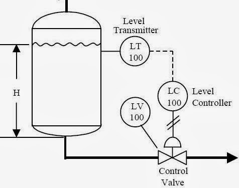
In the above example the tank is filling with the pipe line above the tank and emptying through the bottom pipe line. The level of the liquid in the tank need to control for process purpose. So the control loop is designed here just to control the tank level.

The level or height of the liquid is the process variable here and the level transmitter (LT) is used to measure the process variable continuously.A level controller (LC) is used as controller and a level control valve (LV) is used to control the flow inside the bottom pipe line.

Here the control loop is working in following steps:

  • First the level transmitter (LT) is measuring the level.
  • The measuring value is transmitted to level controller (LC) through electrical signal.
  • The controller decide what to do depending on set or desired value.
  • Then the controller send required command to the level control valve (LV) through a pneumatic signal.
  • Finally the control valve increase or decrease the flow as per controller signal.

P&ID Video

4 Likes

A control loop in a Piping and Instrumentation Diagram (P&ID) represents a system used to control a process variable like temperature, pressure, flow rate, or level.

Control Loop

The basics of a control loop involve four main components:

  1. Process: This is what you’re trying to control. It could be a chemical reaction, the flow of a fluid, a furnace’s temperature, or other industrial processes.
  2. Measurement Device (Sensor): This is a device that measures the process variable. It could be a temperature sensor, pressure sensor, flow meter, or any other type of instrument that measures the state of the process. The measurement is then sent to the controller.
  3. Controller: The controller receives the signal from the measurement device and compares it to a desired set point. If there’s a difference between the measured value and the set point (an error), the controller calculates and sends a corrective output signal to the final control element.
  4. Final Control Element (Actuator): This is a device that can influence the process variable based on the signal received from the controller. It could be a control valve, pump, or a heater. The final control element alters the process to bring it back in line with the desired set point.

This is the basic setup of a control loop. It can be further classified into two types based on the controller action:

  • Feedback Control Loop: The controller acts after the process variable has deviated from the set point. The system measures the actual condition and feeds it back to the controller.
  • Feedforward Control Loop: The controller acts before a change in the process variable occurs. It uses disturbances in the system to predict and prevent deviation from the set point.

Remember that P&IDs are used to illustrate the interconnection of process equipment and the instrumentation used to control the process. In a P&ID, the control loops are usually represented with lines connecting the process, the measurement device, the controller, and the final control element. The specific symbols used can vary somewhat, so the key or legend on the diagram should always be referenced for accurate interpretation.

1 Like