The control configuration for a boiler installation depends on the size of the boiler, the requirements of the insurance company providing coverage for the facility, and the building codes of the locality in which the facility is located.
The overall boiler control system is typically integrated through a control panel known as the burner management system, which controls the boiler operation to maintain the system setpoint conditions and shuts down the boiler if an equipment damaging and life threatening condition is sensed.
For most packaged boiler installations, the basic boiler control is a single -element, proportional control device. In the case of a steam boiler, the control device is a pressure sensing element that sends a signal to the burner management system to adjust the burner firing rate to maintain a set pressure in the steam distribution system.
In a hot water boiler, the control device is a temperature-sensing element. In large steam boiler installations, the control system may be a three-element, proportional-integral-derivative controller that not only responds to the system set pressure, but may also respond to the rate of change in parameters such as pressure, steam flow, or water level.
In multiple boiler installations, the burner management systems of each boiler may be controlled by a master plant controller (sometimes referred to as a lead-lag controller) to stage boiler operation to minimize on/off operation. They may also minimize frequent burner cycling, which can cause thermal stresses leading to tube and tube sheet leaks.
While a brief description of the common types of control components associated with packaged boilers follows, the best guide to facility boiler operation and boiler controls is the manufacturer’s operating and maintenance instructions provided with the boilers.
Figure shows the boiler system’s major components for a Cleaver-Brooks model CB-LE 200 series boilers with a CB-HAWK boiler management control system.
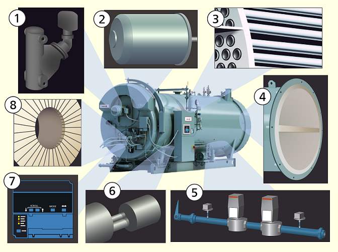
- ‘’‘LOW WATER CUTOFF’’’
- ‘’‘BLOWER MOTOR AND FAN’’’
- ‘’‘TUBES AND TUBE SHEET’’’
- ‘’‘REAR HEAD REFRACTORY’’’
- ‘’‘GAS TRAIN’’’
- ‘’‘BURNER HOUSING AND DIFFUSER’’’
- ‘’‘FLAME SAFEGUARD CONTROLS’’’
- ‘’‘THROAT AND LINER’’’
Common Controls
The following control devices are common to all boilers:
- The ‘’‘forced draft fan motor’’’ drives forced draft fan directly to provide combustion air.
- The ‘’‘forced draft fan motor starter’’’ energizes the forced draft fan motor.
- The ‘’‘forced draft fan’’’ furnishes all air, under pressure, for combustion of pilot fuel and main fuel, and for purging prior to burner ignition and after burner operation termination.
- The ‘’‘ignition transformer’’’ provides high-voltage spark for ignition of the gas pilot or light oil pilot.
- The ‘’‘modulating motor’’’ operates the rotary air damper and fuel valves through a cam and linkage system to provide proper air-fuel ratios under all boiler load conditions.
- The ‘’‘low fire switch’’’ is an internal auxiliary switch, cam-actuated by the modulating motor shaft, which must be closed to indicate that the air damper and fuel metering valve are in the low fire position before an ignition cycle can occur.
- The ‘’‘burner switch’’’ is a manually operated start-stop switch for directly starting and stopping operation of the burner.
- The ‘’‘manual-automatic switch’’’, when set at “automatic,” subsequently operates at the command of the modulating control which governs the position of the modulating motor in accordance with load demand. When set at “Manual,” the modulating motor, through the manual flame control, can be positioned at a desired burner firing rate. The primary purpose of the manual position is for testing and setting the air-fuel ratio through the entire firing range.
- The ‘’‘manual flame control’’’ is a manually operated potentiometer that permits the positioning of the modulating motor to a desired burner firing rate when the manual-automatic switch is set on manual. It is used primarily for initial or subsequent setting of fuel input throughout the firing range. It has no control over the firing rate when the manual-automatic switch is set on “automatic.”
- The ‘’'modulating motor transformer ‘’'reduces control circuit voltage to required voltage for operation of modulating motor (typically reduces 115 volt alternating current to 24 volt alternating current).
- ‘’‘Indicating lights’’’ provide visual information of flame failure, load demand, fuel valve (valve open), and low water.
- The ‘’‘program relay and flame safeguard control’’’ (flame safety system) automatically programs each starting, operating, and shutdown period in conjunction with the operating limit and interlock devices. This includes, in a timed and proper sequence, the operation of the blower motor, ignition system, fuel valve(s), and damper motor. The sequence includes air purge periods prior to ignition and upon burner shutdown. The flame detector portion of this control monitors both oil and gas flames and provides protection in the event of loss of a flame signal. The control recycles automatically during normal operation, or following a power interruption. It must be manually reset following a safety shutdown caused by a loss of flame. An internal checking circuit is incorporated that is effective on every start. The circuit will prevent burner operation in the event anything causes the flame relay to hold in during this period.
- The ‘’‘combustion air proving switch’’’ is a pressure sensitive switch actuated by air pressure from the forced draft fan. Its contacts close to prove presence of combustion air. The fuel valves cannot be energized, unless this switch is satisfied.
- The ‘’‘combustion air damper’’’ controls combustion air in proportion to fuel input for various load demands. The damper may be of the butterfly, opposed blade, or rotary type.
Steam Controls
The following control devices are used with steam systems:
- The ‘’‘steam pressure gauge’’’ indicates boiler internal pressure.
- The ‘’‘operating limit pressure control’’’ breaks a circuit to stop burner operation on a rise of boiler pressure above a selected setting. It is adjusted to stop or start the burner at a preselected pressure setting.
- The ‘’‘high limit pressure control’’’ breaks a circuit to stop burner operation on a rise of pressure above a selected setting. It is adjusted to stop the burner at a preselected pressure above the operating limit control setting. This control is normally equipped with a manual reset.
- The ‘’‘modulating pressure control’’’ senses changing boiler pressures and transmits this information to the modulating motor to change the burner firing rate when the manual-automatic switch is set on automatic.
- The ‘’‘low water cutoff and feed-water pump control’’’ (typically float-operated) responds to the water level in the boiler. The control starts and stops the feedwater pump or operates the feedwater control valve to maintain the proper water level in the boiler. If the water level drops below the lowest safe water level for the boiler, the control shuts down the boiler.
- Most jurisdictions require two independent ‘’‘low water cutoff devices’’’. The auxiliary low water cutoff also provides a signal to shut down the boiler if the water level drops below the lowest safe water level for the boiler.
- The ‘’‘water column’’’ provides visual indication of the boiler water level. The water column and low water cutoff devices for a boiler are typically incorporated in the same piping assembly.
- The ‘’‘test valve’’’ allows the boiler to be vented during filling and facilitates routine boiler inspection. The test valve is typically incorporated in the same piping assembly as the water column and the low water cutoff.
- ‘’‘Safety valves’’’ relieve the boiler of pressure higher than the design pressure. Safety valves and discharge piping must conform to the American Society of Mechanical Engineers (ASME) Boiler and Pressure Vessel Code requirements.
Hot Water Controls
The following control devices are used with hot water systems:
- The ‘’‘water temperature gauge’’’ indicates the internal water temperature.
- The ‘’‘water pressure gauge’’’ indicates the pressure in the boiler.
- The ‘’‘operating limit temperature control’’’ breaks a circuit to stop burner operation on a rise of boiler temperature above a selected setting. It is adjusted to stop or start the burner at a pre-selected operating temperature.
- The ‘’‘high limit temperature control’’’ breaks a circuit to stop burner operation on temperature rise above a selected setting. It is adjusted to stop the burner at a pre-selected temperature above the operating control setting. The high limit temperature control normally is equipped with a manual reset.
- The ‘’‘modulating temperature control’’’ senses changing boiler temperature and transmits this information to the modulating motor to change the burner firing rate when the manual/automatic switch is set on automatic.
- The ‘’‘low water cutoff’’’ breaks the circuit to stop burner operation if the water level in the boiler drops below a safe operating level.
- Most jurisdictions require two independent devices to terminate boiler operation in the event of low water. The ‘’‘auxiliary low water cutoff’’’ also provides a signal to stop burner operation if the water level in the boiler drops below a safe operating level.
- ‘’‘Relief valves’’’ relieve the boiler of pressure higher than the design pressure. Relief valves and discharge piping must conform to the ASME Boiler and Pressure Vessel Code requirements.
Gas Controls
The following control devices are used with ‘’‘gas-fired boilers’’’:
- The ‘’‘gas pilot valve’’’ is a solenoid valve that opens during the ignition period to admit fuel to the pilot. It closes after main flame is established. The sequence of energizing and de-energizing is controlled by the program relay and flame safeguard control. Some jurisdictions may require two independent gas pilot valves installed in series.When two independent gas pilot valves are required, a normally open vent valve is usually required to vent the section of gas piping between the valves whenever both gas pilot valves are de-energized. The vent valve closes when the gas pilot valves are energized.
- The ‘’‘gas pilot shutoff cock’’’ is a manually operated, non-lubricated plug valve for isolating the gas supply from the gas pilot valve.
- The ‘’‘gas pilot adjusting cock’’’ is a manually operated valve used to regulate the size of the gas pilot flame.
- The ‘’‘gas pilot aspirator’’’ is a venturi device using combustion air to improve the flow of gas to the pilot burner.
- The ‘’‘gas pilot pressure gauge’’’ indicates gas pressure in the supply line to the gas pilot.
- The ‘’‘gas pilot pressure regulating valve’’’ reduces incoming gas pressure to suit the requirements of the pilot burner. Most pilot burners require a gas pressure in the range of 5 to 10 inches of water column.
- The ‘’‘main burner gas flow control valve’’’ is modulated through a mechanical linkage to the modulating motor to regulate the flow of gas to the burner in proportion to the boiler load.
- The ‘’‘gas modulating cam’’’ is an assembly consisting of a quadrant, a series of adjustable Allen head screws, and a contour spring to adjust gas input at any boiler load condition to attain the required air-fuel ratio. The position of the quadrant is controlled by the modulating motor.
- The ‘’‘main gas cock’’’ is a manually operated, non-lubricated plug valve for isolating the gas supply from the main gas valves.
- Most jurisdictions require two independent ‘’‘main gas valves’’’ in series. Main valves will open only after the program relay and flame safeguard control signals that a pilot flame has been established.
- The ‘’‘main gas vent valve’’’ is a normally open solenoid valve installed between the two main gas valves to vent gas to atmosphere should any be present in the main gas line when the gas valves are de-energized.
- The ‘’‘low gas pressure switch’’’ is a pressure-actuated switch that is closed whenever the pressure in the gas supply line is above a preselected pressure. If the gas pressure in the gas main drops below the set pressure, the low gas pressure switch opens, breaking the circuit to the main gas valves which causes the main gas valves to close, terminating burner operation.
- The ‘’‘high gas pressure switch’’’ is a pressure-actuated switch that is closed whenever the gas supply line pressure is below a pre-selected pressure. If the gas pressure in the gas main rises above the set pressure, the high gas pressure switch opens breaking the circuit to the main gas valves which causes the main gas valves to close, terminating burner operation.
Oil Controls
The following control devices are used with oil-fired (or dual fuel) boilers:
- The ‘’‘oil drawer switch’’’ is a limit switch which remains open, preventing the burner from operating until the oil drawer burner gun is latched in the forward position.
- The ‘’‘atomizing air proving switch’’’ is a pressure switch that closes allowing the burner to operate when there is sufficient atomizing air pressure for proper burner operation. Oil valve(s) will not operate, or will not remain open, unless the atomizing air proving switch remains closed.
- The ‘’‘air pump module’’’ provides the compressed air required to atomize the fuel oil for proper burner operation. It is started automatically by the program in the program relay and flame safeguard control system.
- The ‘’‘air pump motor’’’ drives the air pump and an air-cooling fan. The control for the motor operates in parallel with the forced draft fan motor.
- The ‘’‘air pump’’’ provides air for atomizing the fuel oil.
- The ‘’‘air filter’’’, typically an oil bath or viscous film filter element, is used to clean the air supply prior to entering the air pump.
- The ‘’‘check valve’’’ prevents lubricating oil and compressed air from surging back through the pump and air filter when the air pump stops.
- The ‘’‘air-oil receiver’’’ tank holds a supply of oil for lubricating the air pump. It separates lube oil from atomizing air before delivery to the burner nozzle.
- The ‘’‘atomizing air pressure gauge’’’ indicates the pressure in the atomizing air supply system near the connection to the burner.
- The ‘’‘lube oil level sight glass’’’ indicates the level of lubricating oil in the air-oil receiver tank.
- The ‘’‘lube oil cooling coil’’’ cools the lubricating oil before the oil enters the air pump. A fan driven by the air pump motor circulates cooling air over the coil.
- The ‘’'lube oil strainer ‘’'filters lubricating oil before the oil enters the air pump.
- The ‘’‘lube oil fill pipe and strainer’’’ are used when adding oil to the air-oil receiver tank.
- Some jurisdictions require a ‘’‘low oil pressure switch’’’. When required, this pressure-actuated switch opens when the pressure in the fuel oil supply system drops below a set value.
- The ‘’‘oil solenoid valve’’’ opens when energized by the program relay and flame safeguard control system allowing fuel oil flow from the oil metering valve to the burner nozzle. Many jurisdictions require two independent oil solenoid valves in series for boiler fired-on light oils.
- The ‘’‘fuel oil controller’’’ is an assembly hat combines the gauges, regulators, and valves required for regulating the flow of fuel oil into a single unit. Most controllers have the following integral parts. In addition to the parts listed below, controllers on systems burning No. 6 or heavier fuel oil require additional parts.’’‘a.’’’ The oil metering valve is operated through a mechanical linkage to the modulating motor. The valve regulates the fuel oil supply to the burner nozzle in proportion to the boiler load.’’‘b.’’’ The oil modulating cam is an assembly consisting of a quadrant, a series of adjustable Allen head screws, and a contour spring to adjust gas input at any boiler load condition to attain the required air-fuel ratio. The position of the quadrant is controlled by the modulating motor.’’‘c.’’’ The oil burner pressure gauge indicates the pressure in the fuel oil supply line at the inlet connection to the oil metering valve.’’‘d.’’’ The oil pressure regulator may be required to reduce the pressure in the facility fuel oil delivery system to a pressure compatible with the oil burner fuel oil supply regulating components.
- The ‘’‘oil relief valve’’’ bypasses excess fuel oil and maintains the fuel oil system pressure indicated on the oil supply pressure gauge.
- When a ‘’‘light oil pilot system’’’ is used, a solenoid valve is provided to control the flow of fuel to the pilot nozzle. The pilot valve is energized at the appropriate time by the program in the program relay and flame safeguard control system. It shuts off the flow of fuel to the pilot when the control system receives a signal that the main burner flame has been established. Note that many oil burners use a gas pilot system.
- The ‘’‘back pressure orifice’’’ is a restriction located in the oil return line immediately downstream of the fuel oil controller to maintain a set pressure in the fuel supply system. A back pressure orifice is generally only used on systems that do not use an oil relief valve.
Heavy Oil Controls
The following additional control devices are used when firing heavy oil:
- The ‘’‘oil heater switch’’’ is a manual disconnect for electric power to fuel oil heater system.
- The ‘’‘oil heater – electric’’’ is used for heating sufficient fuel oil for operating the burner at low fire during cold starts before steam or hot water is available for fuel oil heating. On steam boiler units, the electric heater is typically integral with the steam fuel oil heater. On hot water boiler units, the electric heater is typically a stand-alone unit. The electric heater must be turned off during extended boiler lay-up or at any time fuel oil transfer is terminated.
- The ‘’‘oil heater – steam or hot water’’’ heats the fuel oil to attain the proper fuel oil viscosity for full atomization of the fuel oil. On steam boilers operating at 15 psig or less, the steam heater typically operates at the same pressure as the boiler. On higher pressure steam boiler units, a pressure reducing station is typically installed in the supply line to the fuel oil heater to limit the steam pressure in the oil heater to 15 psig or less.
- The ‘’‘oil heater thermostat – electric and steam’’’ senses fuel oil temperature. On electric heaters, it energizes or de-energizes the electric heater to maintain the proper fuel oil temperature. On steam heaters, it controls the operation of the steam flow control valve in the supply line to the heater to maintain temperature.
- The ‘’‘oil heater thermostat – hot water’’’ – senses fuel oil temperature and starts and stops a booster water pump which circulates hot water from the boiler through the oil heater to control the temperature of the fuel oil.
- The ‘’‘booster water pump’’’ circulates water from the hot water boiler through a hot water fuel oil heater. Operation of the pump is controlled by the hot water oil heater thermostat.
- The ‘’‘oil heater valve’’’ is a normally open solenoid valve opened by the steam boiler heater thermostat to allow flow of steam to the steam heater to maintain the temperature of the fuel oil.
- The ‘’‘steam heater supply check valve’’’ is installed in the steam supply line ahead of a steam oil heater, the check valve prevents oil contamination of the waterside of the pressure vessel should any leakage occur in the oil heater.
- The ‘’‘steam heater pressure regulator’’’ is used on steam boiler units that operate at pressures higher than 15 psig to reduce the steam pressure supplied to the steam oil heater to pressures compatible with the equipment.
- The ‘’‘steam trap’’’ drains condensate and prevents loss of steam from the steam oil heater. The discharge of the steam trap on the steam oil heater unit is typically discharged rather than recovered to eliminate the possibility of contaminating the waterside of the boiler in the event of a leak in the oil heater unit.
- The ‘’‘steam heater discharge check valve’’’ prevents air entry during shutdown periods when cooling action may create a vacuum within the steam heater.
- The ‘’‘oil supply pressure gauge’’’ is installed in the fuel oil supply line between the discharge of the fuel oil heater and the inlet to the fuel oil controller unit oil pressure regulator.
- The ‘’‘low oil temperature switch’’’ is a temperature-actuated switch that prevents the burner from firing or terminates burner operation if the fuel oil temperature is lower than required for proper oil burner operation.
- ‘’‘High oil temperature switch’’’. Some jurisdictions require a temperature-actuated switch that prevents the burner from firing or terminates burner operation if the fuel oil temperature is above a set temperature. This is the high oil temperature switch.
- The ‘’‘fuel oil controller’’’ units for boilers firing heavy oil require the following:’’‘a.’’’ The ‘’‘fuel oil thermometer’’’ indicates temperature of fuel oil being supplied to the fuel oil controller.’’‘b.’’’ The ‘’‘back pressure valve’’’ ensures that a minimum fuel oil supply system pressure is maintained for proper fuel oil controller operation.’’‘c.’’’ The ‘’‘oil return pressure gauge’’’ indicates the oil pressure on the return side of the fuel coil controller.’’‘d.’’’ The ‘’‘manual bypass valve’’’ is used when making a cold start. When open, it bypasses control elements and allows oil circulation through the supply and return system to allow oil heaters to adjust the temperature of the fuel oil before firing the burner is attempted. The valve must be closed prior to firing the boiler.’’‘e.’’’ The ‘’‘orifice oil control valve’’’ may be opened prior to startup to aid in establishing fuel oil flow through the controller. Prior to firing the boiler, the valve must be closed.
- The ‘’‘air purge valve’’’ is a solenoid valve that opens simultaneously with the closing of the oil solenoid valve at burner shutdown, allowing compressed air to purge oil from the burner nozzle and adjacent piping. This oil is burned by the diminishing flame which continues burning for approximately four seconds after the oil solenoid valve closes.
- The ‘’‘air purge orifice nozzle’’’ limits purging air to the proper quantity for expelling unburned oil at the normal delivery rate.
- The ‘’‘air purge orifice nozzle’’’ ‘’‘filter’’’ filters the purging air of any particles that might plug the air purge orifice nozzle.
- The ‘’‘air purge check valve’’’ prevents fuel oil from entering the atomizing airline.
- The ‘’‘air purge relay’’’, when energized, controls the operation of the air purge valve.
Additional Controls for Dual-Fuel Burners
Boilers with dual-fuel burner systems require a selector switch to tell the control system which set of fuel controls to operate.
