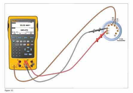
This example assumes that the transmitter is isolated from the process and is not electrically connected to a loop power supply. Make basic connections to the 3144 per the diagram in Figure.
A separate 250 ohm resistor is not necessary because the 754 incorporates a resistor in series with the loop supply through its mA jacks. The 3144 in this example is configured for a type K thermocouple sensor with a span of 0ºC to 300ºC.
Procedure
- Power on the Fluke 754 Calibrator. Press the HART key followed by the Loop Power softkey. Press ENTER to bypass the warning screens and the 754 will display the basic HART information for the 3144.
- Press the HART key again and you are prompted to select the 754 configuration. Selecting MEAS mA, SOURCE T/C typ K configures the calibrator to measure the analog mA output of the transmitter and source the correct temperature stimulus at the 3144 input. (Selecting MEAS PV, SOURCE T/C typ K will configure the 754 to evaluate the digital PV output from the transmitter.) Press ENTER to select.
- Press the As Found softkey, and then press ENTER to select Instrument for a linear transmitter calibration. Notice that the calibration template is automatically completed with the exception of the Tolerance. Fill in the appropriate test tolerance and press the Done softkey.
- Press the Auto Test soft-key to begin calibration. Once the test is complete, an error summary table is displayed. Test errors exceeding the tolerance are highlighted. When done viewing the table, press the Done softkey. Press Done again to accept, or ENTER to change the tag, serial number or ID fields.
- If the As Found test failed (i.e., there were highlighted errors in the error summary table), adjustment is necessary. Press the Adjust softkey. Select Sensor Trim and press ENTER. Select Perform user trim–both and press ENTER.
- For best results, press LRV to apply the LRV for the Lower Trim value. Press Trim and then Continue to move to the Upper Trim. Pres URV press Trim, and then press Done. If the 3144 is used with the digital PV output, skip to step 8 and perform the As Left test. If the analog 4-20 mA output is used in the process, continue on to step 7.
- Select Output Trim and press ENTER. The value of the primary variable (PVAO) is in the upper right corner of the display. This is normally a 4 mA signal. The mA value, as constantly measured by the Fluke 754, is in the center of the display. Press the Fetch softkey to load the measured mA value. Press Send to send the value to the 3144 to trim the output section for the 4 mA value. Press Continue for the 20 mA trim and repeat this step.
- After completing Output Trim, press the Done softkey and proceed with the As Left verification test. Press the As Left softkey. Press Done and then press Auto Test On completion, an error summary table is displayed. If errors are highlighted, the test has failed and further adjustment is required. Return to step 5 for adjustment of the 3144.