We discuss the concept of the PLC ladder logic program, program scanning, and bit instructions.
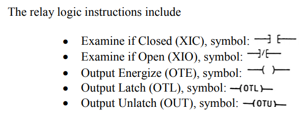
After studying this article, the student will understand how an application program is executed in a PLC. The student will become familiar with the various relay logic instructions. An understanding of how the outputs are affected by the inputs in a ladder logic program, which contains only relay logic instructions, will be gained.
The application program used in PLCs is called the ladder logic program or the ladder diagram. Different brands of PLCs may have different formats for ladder logic programs and instructions, but the formats are similar.
PLC Ladder Logic Program
In this module and in following modules, Allen-Bradley SLC-500 ladder logic programs and instructions are used for examples. The programs used in these examples can be easily converted to other brand PLC ladder logic programs.
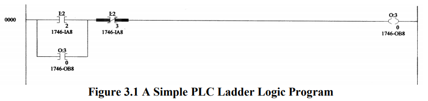
There are two power rails in a ladder logic program. These are the two vertical lines in the program, one on the left, and the other on the right, as shown in Figure 3.1. Each component in a ladder logic program is called an instruction. The instruction or instructions connected in parallel with other instruction(s) create a branch. Each part of the ladder logic program, which is a complete horizontal line and its branch(es) between the two power rails, is called a rung. In Figure 3-1, there is one rung (rung 0000), two branches, and four instructions.
Each of these instructions relates to a single bit of PLC memory that is specified by the instruction’s address. Therefore, these instructions are also called bit instructions. A PLC may have several input modules and several output modules.
Each of the modules takes one slot in the PLC frame. There are usually 8 or more terminals in each module. When an bit instruction uses a memory address assigned to an input terminal, the address format is I:n/m. Here I stands for input, m is the terminal number of the input, and n is the number of the slot where the input terminal is located.
For example, I:2/3 means this is the address of the input terminal 3 in slot 2. When a bit instruction uses a memory address assigned to an output terminal, the address format is O:n/m, Here O stands for output, m is the terminal number of the output, and n is the number of the slot where the output terminal is located.
For example, O:4/5 means this is the address of the output terminal 5 in slot 4. During operation, a PLC processor may set (making logic HIGH) or reset (making logic LOW) a memory bit, based on the inputs and logical conditions of rungs in the program. In a ladder logic program, a relay logic instruction with the same address can be used as many times as the program needs.
An Examine-if-Closed instruction is true when its memory bit is HIGH. The instruction is false when its memory bit is LOW. The logic relation between an Examine-if-Closed instruction and its memory status is similar to the relation between a normally-open relay contact and the relay coil. The normally-open contact is closed (true) when the relay coil is energized (HIGH). The normally-open contact is open (false) when the coil is de-energized (LOW).
An Examine-if-Open instruction is true when its memory bit is LOW. The instruction is false when its memory bit is HIGH. The logic relation between an Examine-if-Open instruction and its memory status is similar to the relation between a normally-closed relay contact and the relay coil. The normally-closed contact is open (false) when the relay coil is energized (HIGH). The normally-closed contact is closed (true) when the coil is de-energized (LOW).
An Output Energize instruction is an instruction being controlled by other instructions. It can only be used at the position next to the right rail in a rung. When there is at least one path made by the instructions that are true from the left rail to the Output Energize instruction, this instruction is true. As long as a true path exists, the Output Energize instruction stays true. When there is not a true path, the Output Energize instruction is false.
Like an Output Energize instruction, an Output Latch instruction needs a true path to get energized. After being energized, this instruction latches itself. Breaking the true path does not cause the energized Output Latch instruction to change to false. The memory bit assigned to an Output Latch instruction can be reset by an Output Unlatch instruction that has the same address as the Output Latch instruction.
An Output Unlatch instruction is used for resetting an output instruction memory. It is usually used in conjunction with an Output Latch instruction. This instruction may only be located next to the right rail in a rung. When there is at least one path made by the instructions that are true from left rail to the Output Unlatch instruction, the instruction activates and resets the memory specified by its address.
When a PLC is executing a ladder logic program, it examines the input modules first. It stores the status (HIGH or LOW) of the input devices, which are connected to the input modules, to memory bits assigned to the inputs.
Then, the PLC scans the ladder logic program rung-by-rung from the top of the program to the bottom. During scanning, the PLC updates the statuses of the instructions in each rung. This will be discussed in the following paragraphs and later modules.
After scanning the entire ladder logic program, the PLC copies the output instruction’s memory statuses (HIGH or LOW) to the output modules to update the output terminals. The period from the beginning of the input terminal examination to the end of the output terminal updates is called a scan cycle. The time required for a scan cycle varies from program to program.
It depends on the length of the program and the instructions used in the program. It may take 20 milliseconds or longer for each scan cycle. When a PLC is in the RUN mode, it executes the ladder logic program stored in its memory. The scan cycle is repeated continuously until the RUN mode is terminated.
When a PLC is scanning a rung, it looks for a path or paths made by the instructions, which are true, from the left rail to the instruction next to the right rail. If there is at least one true path, this rung is true and the instruction next to the right rail is set as true, or enabled. If there is not a true path, this rung is false and the instruction next to the right rail is set as false, or disabled. This instruction’s memory is updated right after the PLC scans the rung.
In Figure 3.1, the status of Output Energize instruction O:3/0 depends on the statuses of the Examine-if-Open instruction I:2/3 and the Examine-if-Closed instructions I:2/2 and O:3/0. In the following table, the first three columns of each row list a logic status combination of the Examine-if-Open instruction I:2/3 and the Examine-if-Closed instructions I:2/2 and O:3/0. The last column of that row shows the corresponding logic status of the Output Energize instruction O:3/0.
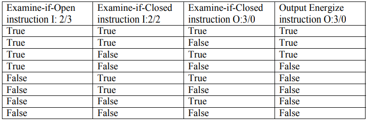
In the first three rows of the table, there is at least one true path from the left rail to the Output energize instruction O:3/0. Therefore, the Output Energize instruction O:3/0 is true. In the last five rows of the table, there is no true path from left rail to the Output Energize instruction O:3/0. The Output Energize instruction O:3/0 in this case is therefore false.
The ladder logic program in Figure 3.1 is an output latch control. Each of the input terminals I:2/2 and I:2/3 is connected to a normally-open, momentarily-closed push button. A normallyopen, momentarily-closed push button is a control component, whose contacts are open when the button is not pushed. Its contacts are closed when the button is pushed.
The output terminal O:3/0 is connected to the device being controlled, e.g. a motor starter, a heater, a light, or similar device. The push button connected to the input terminal I:2/2 is a START button. When this button is pressed and the button connected to the input terminal I:2/3 is not pressed, the PLC finds a true path made by the Examine-if-Closed instruction I:2/2 and the Examine-if-Open instruction I:2/3.
So the Output Energize instruction O:3/0 is true now and its memory is updated. This memory updating causes the Examine-if-Closed instruction O:3/0 to be true. Now, releasing the START button does not cause the Output Energize instruction O:3/0 to turn to false, because there is another true path made by the Examine-if-Closed instruction O:3/0 and the Examine-if-Open instruction I:2/3.
The push button connected to the input terminal I:2/3 is a STOP button. When this button is pressed, the Examine-if-Open instruction I:2/3 is false. That will cut off the true path to the Output Energize instruction O:3/0 and de-energize the output.
Figure 3.2 is a ladder logic program that does the same function as the one in Figure 3.1. In this program, a bit instruction with the address of B3:1/10 is used. The Output Energize instruction B3:1/10 in Figure 3.2 works similarly to the Output Energize instruction O:3/0 in Figure 3.1. That means B3:1/10 is true when its rung is true, and B3:1/10 is false when its rung is false.
However, a bit instruction with the address beginning with the letter B only affects a memory location. This memory location does not link to an output terminal. Therefore, the status of Output Energize instruction B3:1/10 does not control an output device unless it is also used in another rung(s) of the program for controlling other instruction(s).
The second rung of Figure 3.2 uses the Examine-if-Closed instruction B3:1/10 to control the Output Energize instruction O:3/0. When B3:1/10 is true, O:3/0 is also true. The bit instructions that have addresses beginning with a letter B are used for program internal control.
That allows PLC programmers not to use any output terminal address if there is not a device needed to be controlled by the output instruction.
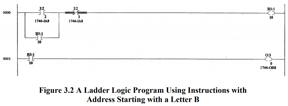
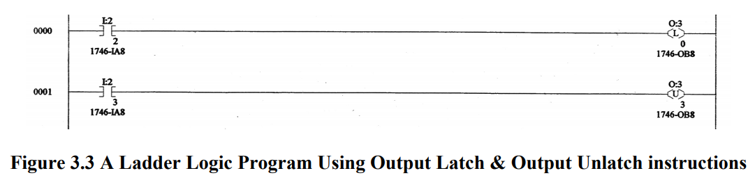
Figure 3.3 is another ladder logic program that performs the same function as the one in Figure 3.1. In this program, Output Latch instruction and Output Unlatch instruction are used. When the Examine-if-Closed instruction I:2/2 in the first rung is true, the Output Latch instruction O:3/0 is true and latched.
Even though Examine-if-Closed instruction I:2/2 becomes false later, the output memory O:3/0 remains true because it has been latched. This memory can only be reset when the Output Unlatch instruction with the same address is activated. In this program, when the Examine-if-Closed instruction I:2/3 is true, the output memory O:3/0 is reset.