Ladder logic rungs should be formatted so the reader can easily infer the meaning of the intended logic.
Designing PLC ladder Logic
One mechanism to help this is the grouping of related signals within an area on a given rung of logic.
For example:
Group signals together that have some common intent
• Start signals
• Stop signals
• Emergency stop signals (E-stop)
• Interlocks
Controls that might have greater importance (i.e. E-stop) might be located on the left hand side of the rung if possible.
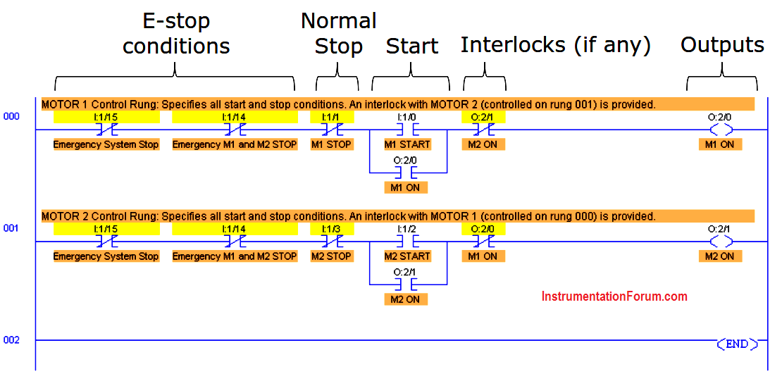
This is also a good example of instruction and rung documentation.
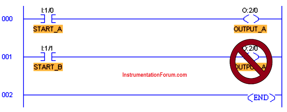
An output energize instruction (OTE) referencing a specific output bit should appear only once in a ladder logic program.
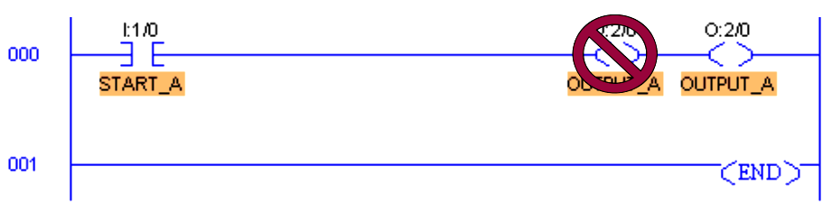
Only one output energize instruction (OTE) should appear in a rung of ladder logic.