Amplitude Shift Keying
In amplitude shift keying, the amplitude of the carrier signal is varied to create signal elements. Both frequency and phase remain constant while the amplitude changes.
Binary ASK (BASK)
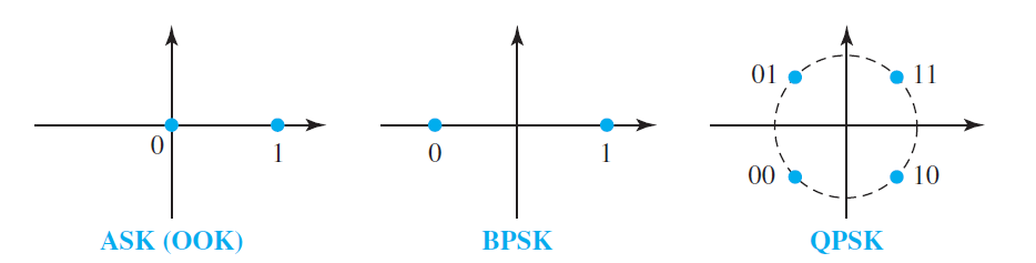
Although we can have several levels (kinds) of signal elements, each with a different amplitude, ASK is normally implemented using only two levels. This is referred to as binary amplitude shift keying or on-off keying (OOK). The peak amplitude of one signal level is 0; the other is the same as the amplitude of the carrier frequency.
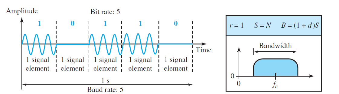
Bandwidth for ASK
As we expect, the bandwidth is proportional to the signal rate (baud rate). However, there is normally another factor involved, called d, which depends on the modulation and filtering process. The value of d is between 0 and 1. This means that the bandwidth can be expressed as shown, where S is the signal rate and the B is the bandwidth.
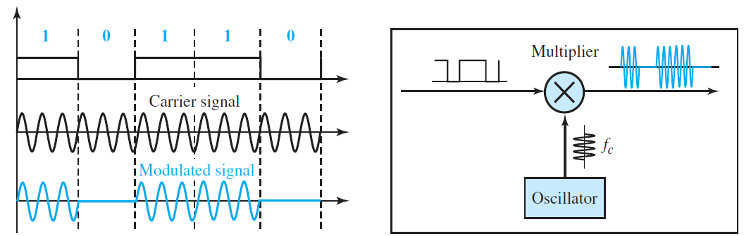
Implementation
Frequency Shift Keying
In frequency shift keying, the frequency of the carrier signal is varied to represent data. The frequency of the modulated signal is constant for the duration of one signal element, but changes for the next signal element if the data element changes. Both peak amplitude and phase remain constant for all signal elements.
Binary FSK (BFSK)
One way to think about binary FSK (or BFSK) is to consider two carrier frequencies. We have selected two carrier frequencies, f1 and f2. We use the first carrier if the data element is 0; we use the second if the data element is 1. However, note that this is an unrealistic example used only for demonstration purposes. Normally the carrier frequencies are very high, and the difference between them is very small.

The middle of one bandwidth is f1 and the middle of the other is f2. Both f1 and f2 are Δf apart from the midpoint between the two bands. The difference between the two frequencies is 2Δf.
Bandwidth for BFSK
There are two implementations of BFSK: noncoherent and coherent. In noncoherent BFSK, there may be discontinuity in the phase when one signal element ends and the next begins. In coherent BFSK, the phase continues through the boundary of two signal elements. Noncoherent BFSK can be implemented by treating BFSK as two ASK modulations and using two carrier frequencies. Coherent BFSK can be implemented by using one voltage-controlled oscillator (VCO) that changes its frequency according to the input voltage.
Phase Shift Keying
In phase shift keying, the phase of the carrier is varied to represent two or more different signal elements. Both peak amplitude and frequency remain constant as the phase changes. Today, PSK is more common than ASK or FSK. However, we will see shortly that QAM, which combines ASK and PSK, is the dominant method of digital-to-analog modulation.
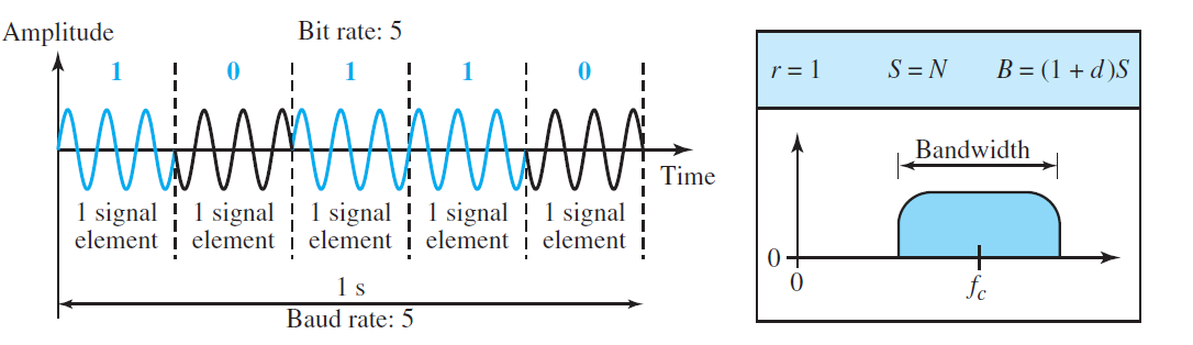
Binary PSK (BPSK)
The simplest PSK is binary PSK, in which we have only two signal elements, one with a phase of 0°, and the other with a phase of 180°. Figure gives a conceptual view of PSK. Binary PSK is as simple as binary ASK with one big advantage—it is less susceptible to noise. In ASK, the criterion for bit detection is the amplitude of the signal; in PSK, it is the phase. Noise can change the amplitude easier than it can change the phase. In other words, PSK is less susceptible to noise than ASK. PSK is superior to FSK because we do not need two carrier signals. However, PSK needs more sophisticated hardware to be able to distinguish between phases.

Bandwidth
Figure also shows the bandwidth for BPSK. The bandwidth is the same as that for binary ASK, but less than that for BFSK. No bandwidth is wasted for separating two carrier signals.
Quadrature PSK (QPSK)
The simplicity of BPSK enticed designers to use 2 bits at a time in each signal element, thereby decreasing the baud rate and eventually the required bandwidth. The scheme is called quadrature PSK or QPSK because it uses two separate BPSK modulations; one is in-phase, the other quadrature (out-of-phase). The incoming bits are first passed through a serial-to-parallel conversion that sends one bit to one modulator and the next bit to the other modulator. If the duration of each bit in the incoming signal is T, the duration of each bit sent to the corresponding BPSK signal is 2T. This means that the bit to each BPSK signal has one-half the frequency of the original signal.
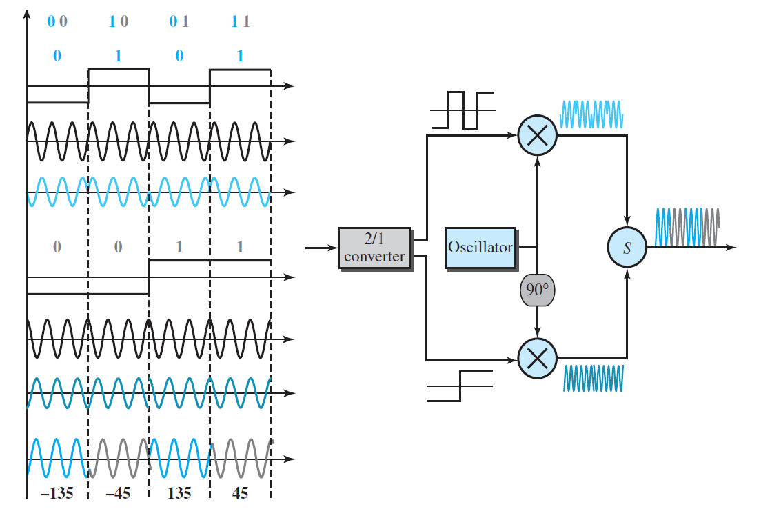
The two composite signals created by each multiplier are sine waves with the same frequency, but different phases. When they are added, the result is another sine wave, with one of four possible phases: 45°, −45°, 135°, and −135°. There are four kinds of signal elements in the output signal (L = 4), so we can send 2 bits per signal element (r = 2).
Constellation Diagram
A constellation diagram can help us define the amplitude and phase of a signal element, particularly when we are using two carriers (one in-phase and one quadrature). The diagram is useful when we are dealing with multilevel ASK, PSK, or QAM. In a constellation diagram, a signal element type is represented as a dot. The bit or combination of bits it can carry is often written next to it.
The diagram has two axes. The horizontal X axis is related to the in-phase carrier; the vertical Y axis is related to the quadrature carrier. For each point on the diagram, four pieces of information can be deduced. The projection of the point on the X axis defines the peak amplitude of the in-phase component; the projection of the point on the Y axis defines the peak amplitude of the quadrature component. The length of the line (vector) that connects the point to the origin is the peak amplitude of the signal element (combination of the X and Y components); the angle the line makes with the X axis is the phase of the signal element. All the information we need can easily be found on a constellation diagram.
Source: Forouzan Behrouz