This method is based on the application of the Archimedes’ principle: every body immersed in the liquid or gas is exposed to the action of a buoyant force (sometimes called as the Archimedes’ force), which acts upwards.
This force is equal to the weight of the liquid, gas or vapour displaced by this body. The immersed body is called a buoy, thus giving the name to the method of measurement. Fig. presents a schematic of this type of device.
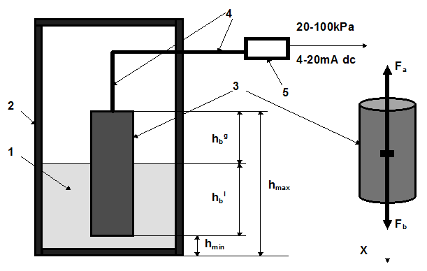
To measure the level of liquid 1 in a tank 2 a buoy 3 is partly immersed in the liquid. When the level varies so does the resultant force acting on the buoyancy/displacer.

The displacer element, buoy, is a cylinder of a constant cross-section area, and its density is greater than that of the liquid. The buoy moves up or down, depending on the level variation. The resultant force through a lever 4 is converted by a force-balance or electronic transmitter 5 to a proportional pneumatic (20-100 kPa) or electrical (4-20 mA dc) signal, which is transmitted by the distance. It means that for each value of the level in the tank will correspond the certain value of an output signal.
The length, diameter, material of the buoy and transmission ratio can be changed to suit various spans and various liquids. These instruments are used for measurements of liquid level and interface providing the level to vary within the length of the buoy, and for density measurements providing the buoy is fully immersed in liquid in the entire range of measured densities.
It is appropriate now to consider an operational principle of a pneumatic transmitter, which is used for converting level variations into the standard pneumatic signal. To be more precise, these transmitters can be used to convert a mechanical motion (which may be caused by the variation of any process variable) into the standard pneumatic signal. Fig. 5.3 shows a schematic view of the pneumatic transmitter.
When level of the liquid goes up, the Archimedes’ force moves the buoy 1 in the same direction. A membrane 2 separates the measuring part of the pneumatic transmitter from the part with a high process pressure in the tank where the level is to be measured. The motion of the buoy through levers 3 (rotates clockwise) and 4 (rotates clockwise) transmits to the force bar 5 (rotates clockwise). The force bar is connected with the flapper 6, which approaches to the nozzle 7. The pressure supplied to a pneumatic amplifier 8 is equal to 140 kPa. The pressure from this amplifier is fed to the nozzle, and then to atmosphere. When the flapper approaches to the nozzle, the pressure in the nozzle increases. This pressure enters the pneumatic relay in the pneumatic amplifier, where it is amplified, and so the value of the output pressure increases.
The output pressure is transmitted to a measuring or controlling instrument, and is applied to the feedback bellows 9, thus increasing the counterclockwise moment of force acting from the lever 10 (rotates clockwise) on the force bar 5. This moment of force is sufficient to restore the force bar to the balance. When the balance has reached the output pressure is linearly related to the value of the measured liquid level. A gain adjustment holder 11 is used for the variation of the measuring range. An additional weight 12 is used for damping the vibration of levers. Zero adjustment can be achieved by the spring 13.