Control level of given continuous process using DCS
DCS (Distributed Control System) is a computerized control system used to control the production line in the industry.
Why DCS System is required?
While a product (Food, medicine, Oil…etc) passing through many stages in the factory before it reaches it’s final so the product can be sold out, during those stages it requires a kind of control in order to adjust the quality of it. However, to adjust the quality it is required to control many physical quantities such as pressure, Temperature…etc.
Further more, in some dangerous applications such as petrochemical factories and nuclear reactors the control will much critical, However, losing the control may lead to an explosion of the plant.
What does DCS System consists of?
DCS System consists minimum of the following components.
-
Field Control station (FCS): It consists of input/output modules, CPU and communication bus.
-
Operator station: It is basically human interface machine with monitor, the operator man can view the process in the plant and check if any alarm is presents and he can change any setting, print reports…etc.
-
Engineering station: It is used to configure all input & output and drawing and any things required to be monitored on Operator station monitor.
How does it work?
Basically, DCS system receives input signals from other devices, these signals will be processed and analyzed by DCS CPU and based on the result an action will be taken.
There are many sensors and transducersinside the plant converts physical quantities such as pressure, temperature to an electrical quantity, these devices called Transmitters they transmit the electrical signals represents physical quantities to DCS System.
There could be thousand of transmitters in a factory sending signals to DCS. The electrical signals could be either analog or digital, for analog signals they could be in one of the following cases.
- 4 to 20mA, 1 to 5VDC or Resistance.
- And for digital they would be either logic 0 or logic 1.
When FCS receives the analog signals from different transmitters it will convert it to digital via input module then passed to CPU for processing, the CPU will compare the process measured value (PV) with value sited by the operator (SV). If the both values are not matched then DCS will generate an output called Manipulated value (MV) to the field via output modules in order to adjust the physical quantity by operating a valve for example.
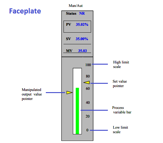
Example of simple control mechanism. The water in the tank is required to be controlled, the level transmitter will measure the water level and send PV signal (4- 20mA) to DCS. Input module in the FCS will receive this signal and pass it to CPU after converting it to digital signal. The PV data can be monitored on operator station screen in small window called Faceplate.
On the faceplate the operator can see the three parameters reading SV, PV & MV at the top. The SV can be set to the required level by moving the yellow pointer. DCS system will operate the pump by sending MV Signal via output module to fill the tank and continue as long as PV signal received from the transmitter is less then SV, once the water level reached to required level that means PV=SV the DCS will stop the pump and this happen if faceplate mode is Auto, however in Manual mode, the operator can control MV directly and SV pointer will be disabled.
Also the faceplate shows the status of this control process Normal or Alarm, the alarm status will be initiated if there is any problem in which PV is not able to equalize with SV.