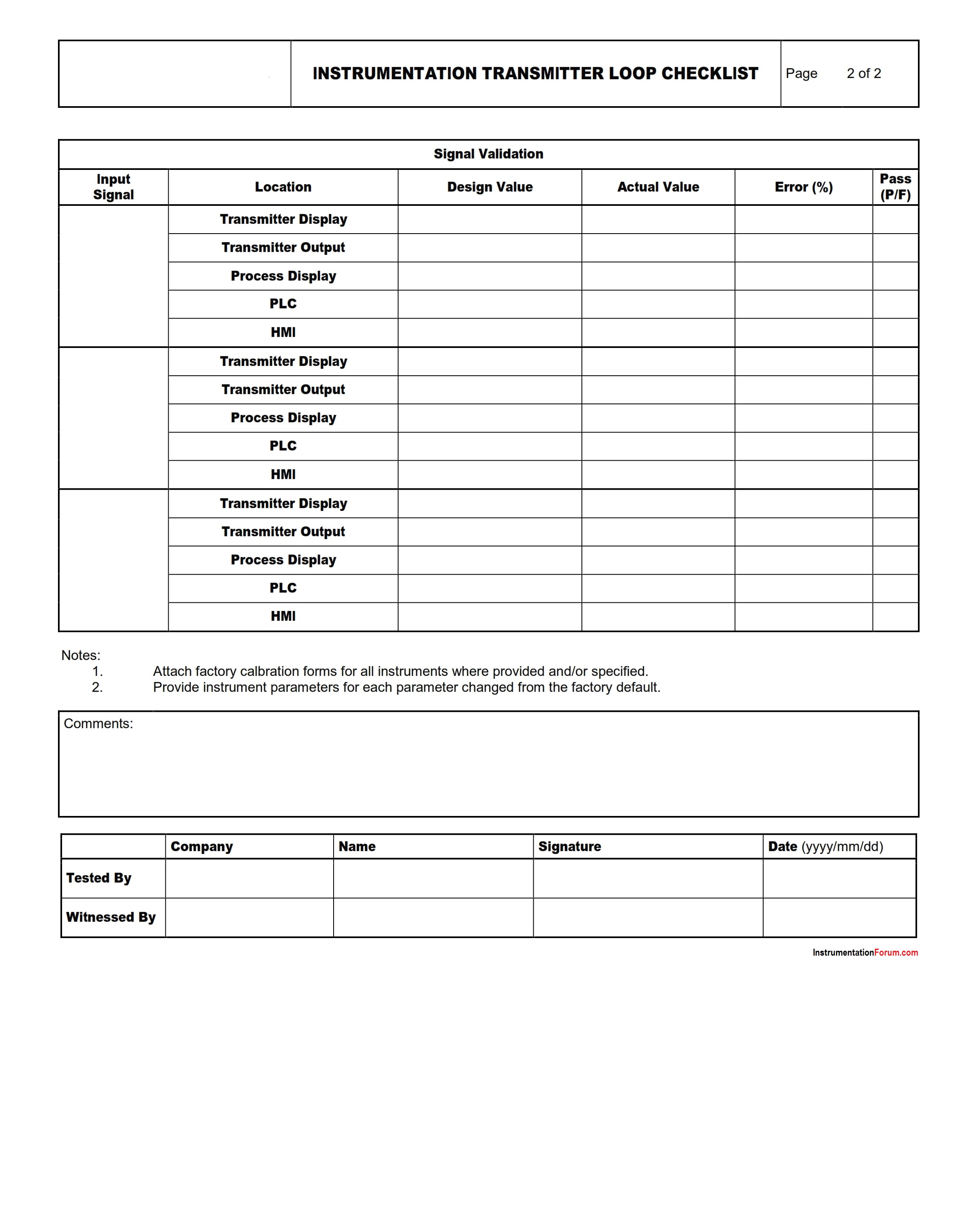
The Instrumentation Transmitter Loop checklist is used to verify the installation of field instruments, configuration, and calibration validation and functional testing.
Inspection Checklist for Transmitter
- Instrument type and class per P&ID and specification
- Instrument tag(s) installed and correct
- Installation of sensor complete and correct
- Block and drain valves
- Pneumatic / hydraulic tubing leak tested
- Heat tracing / insulation / instrument housing
- Impulse lines pressure tested
- Wiring correct
- Drawings marked up as-built
- HMI Graphic symbol, tag and units correct
Download Checklist for Instrumentation Transmitter Loop
6 Likes
An instrumentation transmitter loop, often referred to as a 4-20mA loop, is a common component in industrial process control systems.
The transmitter measures a process variable (like temperature, pressure, level, or flow), converts it into an electrical signal, and sends it to a receiving device such as a controller, indicator, or recorder.
Instrumentation Transmitter Loop
Here’s a basic checklist for reviewing an instrumentation transmitter loop:
-
Transmitter Installation and Mounting: Check if the transmitter is installed correctly according to the manufacturer’s instructions and if it’s mounted in a stable and secure manner.
-
Wiring and Connections: Confirm that all the wiring is correct and secure. Ensure the correct polarity for DC systems.
-
Power Supply: Ensure the power supply is connected, turned on, and providing the correct voltage. For a 4-20mA loop, the power supply is typically 24V DC.
-
Loop Current: Test the loop current with a multimeter to confirm it’s within the expected range (4-20mA). Check if the loop current changes correctly with variations in the process variable.
-
Transmitter Calibration: Check if the transmitter is calibrated correctly. The output current should correspond correctly to the measured process variable. This can be tested using a calibration tool to simulate the process variable and observe the output.
-
Loop Resistance: Check the total resistance of the loop to make sure it’s within the allowable range. Remember that the resistance of the loop includes the resistance of the wire, the input resistance of the receiving device, and any other devices connected in the loop.
-
Grounding and Isolation: Check for proper grounding and isolation to avoid electrical noise and ensure accurate measurement.
-
Environment Conditions: Check if the transmitter is suitable for the ambient conditions (temperature, humidity, etc.) and the process conditions (corrosive substances, high pressure, etc.).
-
Safety and Compliance: Ensure the system meets safety requirements and complies with any relevant standards or regulations.
-
Documentation: Make sure the documentation (P&IDs, loop diagrams, datasheets, etc.) matches the installed system.
Remember that the exact checklist may vary based on the specific type of transmitter and the details of the system. Always follow the manufacturer’s guidelines and local regulations.
1 Like