- A drawing which shows the relative locations of various components is a:
A. Wiring diagram
B. Schematic diagram
C. Elementary diagram
D. Ladder diagram
- To ensure safety for maintenance, the motor disconnecting switch must be locked in the
“OFF” position. After the maintenance work is completed, the lock is removed by:
A. The supervisor
B. The project manager
C. The person who put the lock on
D. The lead hand
- With regard to workers safety, “isolation” refers to:
A. Moving to a remote location
2. Disconnect from all energy sources
3. Turn off the electrical switch
4. Fence off the work site
-
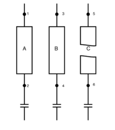
Referring to the drawing, assuming that fuse C is blown, which pair of points will result in a reading of zero volts when the voltmeter is connected across them?
-
The disconnecting means which is NOT intended for interrupting current flow is the:
-
Motor switch
-
General use switch
-
Isolating switch
-
Circuit breaker
-
If the circuit in the drawing was operating normally and an overload occurred, then:
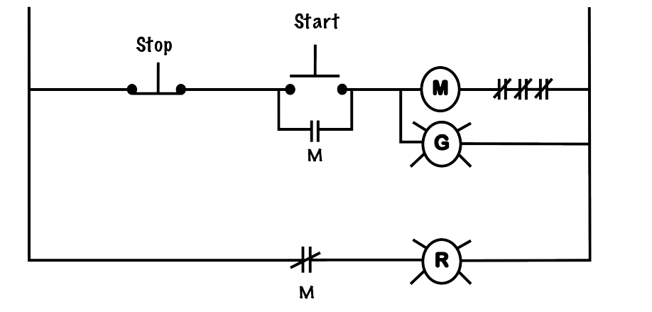
A. Both lights would come on
B. The green light would come on, and the red light would go out
C. Both lights would go out
D. The red light would come on, and the green light would go out
- During normal operation, a loud chattering noise is heard from the enclosure of an AC
magnetic starter. What is the most likely cause?
A. Broken shading coil
B. Open in the seal-in circuit
C. Rust on pole faces
D. Power contact is not making good contact due to poor pressure
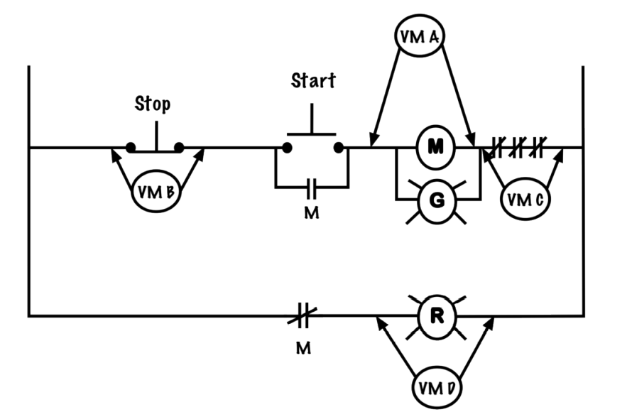
- If the control circuit shown below tripped due to overload, then which of the voltmeter
positions shown would indicate line voltage?
-
VM A
-
VM B
-
VM C
-
VM D
-
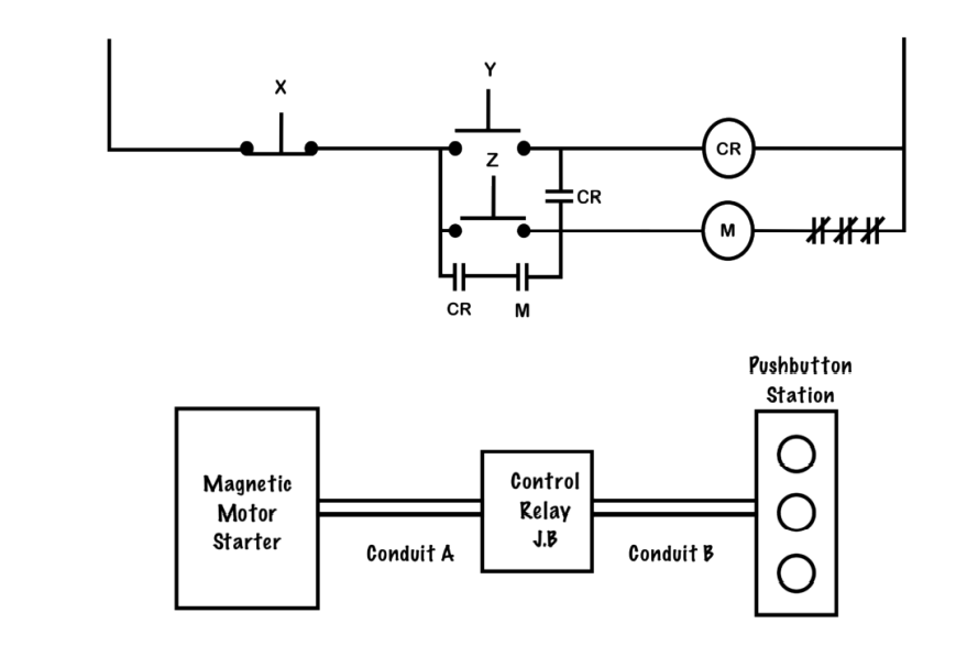
What is the minimum number of control circuit conductors required in Conduit A?
A. 2 wires
B. 3 wires
C. 4 wires
D. 5 wires
- An isolating switch can be used as a motor power circuit disconnect switch. True or false? Use the following image to answer questions 11 and 12.

- If the motor starter in the drawing is energized and functioning properly, what should the voltage be across the normally open contact (M)?
A. Line voltage
B. Zero voltage
C. Half of line voltage
D. Twice line voltage
- If the motor starter in the drawing is energized and functioning properly, what should be the voltage across the N.C contact (M)?
A. Line voltage
B. Zero voltage
C. Half of line voltage
D. Twice line voltage
Answers
- A
- C
- B
- 3 and 6
- C
- D
- A
- ?
- ?
- False
- B
- A
Reference
Basic Motor Control by Aaron Lee and Chad Flinn is used under a CC BY 4.0 Licence.