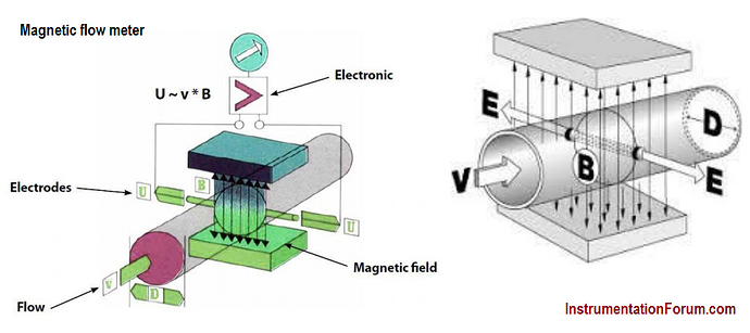
The operation of a magnetic flow meter or mag meter is based upon Faraday’s Law, which states that the voltage induced across any conductor as it moves at right angles through a magnetic field is proportional to the velocity of that conductor.
Faraday’s Formula, E =C x V x B x L
where: E = The voltage generated in a conductor, C= Constant,
V = The velocity of the conductor, B = The magnetic field strength L = The length of the conductor
Magnetic flow meter
To apply this principle to flow measurement with a magnetic flowmeter, it is necessary first to state that the fluid being measured must be electrically conductive.
As applied to the design of magnetic flowmeters, Faraday’s Law indicates that signal voltage (E) is dependent on the average liquid velocity (V) the magnetic field strength (B) and the length of the conductor (L) (which in this instance is the distance between the electrodes).
Construction:
-
The magnetic flowmeter consists of an electrically insulated or non conducting pipe such as fiber glass.
-
A pair of electrodes mounted opposite to each other and flush with the inside walls of its pipe
-
Magnetic coil mounted around the pipe so that a magnetic field is generated in a plane mutually perpendicular to the axis of the flowmeter body and to the plane of electrodes.
-
If a metal pipe is used, an electrically insulating liner is provided to the inside of the pipe. A cut way view of the magnetic flow meter is shown in Fig. 1.
-
Flowing liquid acts as the conductor, the length L is the distance between the electrodes and equals to the pipe diameter.
-
The magnetic coils may energized either by AC or DC voltage, but the recent development is the pulse DC-type in which the magnetic coils are periodically energized.
Working:
-
As conductive fluid passes through the electrodes and magnetic field, voltage is generated at tip of electrodes.
-
Magnetic meters are available in sizes from 2.54 to 2540 mm in diameter, with an accuracy range ±1/2 to ±2%. The rangeability of such meters may be 30:1, however, normally accepted range is about 20:1. The measurement of these meters are independent of viscosity, density, temperature and pressure.
-
In a new design of magnetic flowmeter, it can be inserted into the line through couplings. It consists of electrodes mounted on each side of the probe and magnetic coils which are also integral to the probe. The probe can be mounted on pipes of any size, and can easily be mounted for open channel flow.
Advantages:
-
They consist of no moving parts; hence there are no restrictions to the flow.
-
They are competent enough to measure intricate and corrosive liquids and slurries.
-
Moreover, they are capable of measuring forward as well as reverse flow with the same accuracy.
-
Initial designs of electromagnetic flowmeters involved high power consumption and zero meter settings (i.e. no flow to initially set the meter to zero). However, advanced designs have eradicated all these problems. New Pulse-type excitation techniques have reduced power consumption to a great extent. Zero meter settings are also no longer mandatory
Disadvantages:
- It is relatively expensive.
- It works only with fluids which are adequate electrical conductors.
- It is relatively heavy, especially in larger sizes.
- It must be full at all times.
- It must be explosion proof when installed in hazardous electrical areas.
