
A thermal power station is a power plant in which heat energy is converted to electric power. In most of the world the turbine is steam-driven. Water is heated, turns into steam and spins a steam turbine which drives an electrical generator. After it passes through the turbine, the steam is condensed in a condenser and recycled to where it was heated; this is known as a Rankine cycle. The greatest variation in the design of thermal power stations is due to the different heat sources, fossil fuel dominates here, although nuclear heat energy and solar heat energy are also used. Some prefer to use the term energy center because such facilities convert forms of heat energy into electrical energy
Selection of site for thermal power plant
Transportation network: Easy and enough access to transportation network is required in both power plant construction and operation periods.
Gas pipe network: Vicinity to the gas pipes reduces the required expenses.
Power transmission network: To transfer the generated electricity to the consumers, the plant should be connected to electrical transmission system. Therefore the nearness to the electric network can play a roll.
Geology and soil type: The power plant should be built in an area with soil and rock layers that could stand the weight and vibrations of the power plant.
Earthquake and geological faults: Even weak and small earthquakes can damage many parts of a power plant intensively. Therefore the site should be away enough from the faults and previous earthquake areas.
Topography: It is proved that high elevation has a negative effect on production efficiency of gas turbines. In addition, changing of a sloping area into a flat site for the construction of the power plant needs extra budget. Therefore, the parameters of elevation and slope should be considered.
Rivers and floodways: obviously, the power plant should have a reasonable distance from permanent and seasonal rivers and floodways.
Water resources: For the construction and operating of power plant different volumes of water are required. This could be supplied from either rivers or underground water resources. Therefore having enough water supplies in defined vicinity can be a factor in the selection of the site.
Environmental resources: Operation of a power plant has important impacts on environment. Therefore, priority will be given to the locations that are far enough from national parks, wildlife, protected areas, etc.
Population centers: For the same reasons as above, the site should have an enough distance from population centers.
Need for power: In general, the site should be near the areas that there is more need for generation capacity, to decrease the amount of power loss and transmission expenses.
Climate: Parameters such as temperature, humidity, wind direction and speed affect the productivity of a power plant and always should be taken into account.
Land cover: Some land cover types such as forests, orchard, agricultural land, pasture are sensitive to the pollutions caused by a power plant. The effect of the power plant on such land cover types surrounding it should be counted for.
Area size: Before any other consideration, the minimum area size required for the construction of power plant should be defined.
Distance from airports : Usually, a power plant has high towers and chimneys and large volumes of gas. Consequently for security reasons, they should be away from airports.
Archeological and historical sites: Usually historical building …are fragile and at same time very valuable. Therefore the vibration caused by power plant can damage them, and a defined distance should be considered.
Schematic of a Thermal Power Plant

Figure 01: Rankine Cycle and Thermal Power Plants

Figure 02: Schematic of a Thermal Power Plant-2
Major Components of a Thermal Power Plant
Coal Handling Plant
Pulverizing Plant
Draft or Draught fan
Boiler
Ash Handling Plant
Turbine and Generator
Condenser
Cooling Tower And Ponds
Feed Water Heater
Economiser
Super heater and Reheater
Air pre heater
Alternator with Exciter
Protection and control equipment
Instrumentation
Coal Handling Plant

Figure 03: Coal Handling Plant

Figure 04: Coal Storage

Figure 05: Processing in Coal Handling Plant
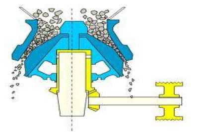
Figure 06: Impact Crushers
Stacking Process:
This process involves in dead storage in the form of piles laid directly in the ground. In case of road transport and aerial transport coal are unloaded in stack yard and the coal is stacked properly using dozers.
When coal supply by railway is excess it would be stacked through a separate conveyor. For these purpose stacker or telescopic chutes are used.
Reclaiming Process:
The stored coal is required to bunkered in case of emergency or improper coal supply. The reclaiming process involves the lifting of coal from stack yard by means of dozer or reclaimer like bucket wheel.
The dozer feed this coal in hopper. This process is simple process. This process is simple. The main object of this process to bunker crush coal or non-crush coal as per requirement of bunker to support the other process feeding.
Bunkering Process:
This process involves feeding of bins and maintaining the level of these bins. From the
conveyor belt the coal is discharged into bunker or bins with the help of trippers.
Draught System
The combustion in the boiler requires supply of sufficient quality of air and removal of
exhaust gases
The Circulation of air is caused by difference of pressure is known as draught. Thus draught
is the differential in pressure between the two points.
A draught tube may be
-
Natural Draught
-
Mechanical Draught
Natural Draught
A natural Draught is provided by the chimney or stack.
Natural draught has its limitation . Modern plants has high rate of heat transfer and Draught losses are very high. in view of this Natural draught is used only for small boilers.
Mechanical Draught
Modern large size plants use very large size of boilers of capacity above 1000,000 kg per hour. Such boiler needs tremendous volume of air (around 200000 m3) Per minute. A chimney provide this. Therefore mechanical draught is used.
In a mechanical draught the system the movement air is due to the action of fan. A mechanical Draught consist of forced Draught or induced draught or both.
In forced draught system the fan is installed near the boiler .the fan force the air through the furnace, economizer, air preheater and chimney. The pressure of air, throughout the system, is above atmospheric and air is forced to flow through the system
In an induced draught system the, the fan is installed near the base of the chimney .The burnt gases are sucked out from the boiler, thus reducing the pressure inside the boiler to less than atmosphere, this induces fresh air to enter the furnace.
A mechanical Draught need additional capital investment and maintenance .But it required for proper operation of modern power plant. In super thermal power plant, each boiler may used two forced fans and two induced fan.

Figure 07: Draught System
Boiler
A boiler (or steam generator) is a closed vessel in which water, under pressure, is converted into steam. The heat is transferred to the boiler by all three modes of heat transfer i.e. conduction convection and radiation.
Major types of boilers are: (i) fire tube boiler and (ii) water tube boiler
Fire Tube Boiler
The boiler is named so because the production of combustion pass through the tubes which are surrounded by water.
Depending on whether the tube is vertical or horizontal the fire tube boiler is divided into two types
Vertical tube boiler
Horizontal tube boiler
A fire tube boiler is simple, compact and rugged in construction. Its initial cost is low.

Figure 08: Fire Tube Boiler
Water Tube boilers
In this boiler, the water flows inside the tubes and hot gases flow outside the tube .
Water tube boiler are classified as
Vertical tube boiler
Horizontal tube boiler
Inclined tube boiler
The circulation of water in the boiler is may be natural or forced.

Figure 09: Water Tube Boiler
Superheater and Reheaters
Superheated steam is that steam which contains more heat than the saturated steam at the same pressure. The additional heat provide more energy to the turbine hence power output is more.
Superheated steam causes lesser erosion of the turbine blades and can be transmitted for longer distance with little heat loss
The function of the super heater is to remove the last trash of moisture from the saturated steam.
A superheater may be convention type, radiant type or combination

Figure 10: Functions of superheater

Figure 11: Superheater
Reheater
In addition to super heater modern boiler has reheater also. The function of the reaheater is to superheat the partly expanded steam from the turbine, this ensure that The steam remain dry through the last stage of the turbine.
A reheater may be convention type, radiant type or combination
Feed Water Heaters
Feed Water heating improve overall efficiency.
The dissolved oxygen which would otherwise cause boiler corrosion are removed in the feed water heater.
Thermal stresses due to cold water entering the boiler drum are avoided.
Quantity of steam produced by the boiler is increased.
Some other impurities carried by steam and condensate, due to corrosion in boiler and condenser, are precipitated outside the boiler.

Figure 12: Water steam flow diagram
Economizer
Boilers are provided with economizer and air pre-heaters to recover heat from the flue gases. An increase of about 20% in boiler efficiency is achieved by providing both economizer and air pre-heaters.
Economizer alone gives only 8% efficiency increase. The feed water from the high pressure heaters enters the economizer and picks up heat from the flue gases after the low temperature superheater.
Economizer can be classified as an inline or staggered arrangement based on the type of tube arrangement.

Figure 13: Economizer
Air Preheaters
After the flue gases leave economizer, some further heat can be extracted from them and is used to heat the incoming air for combustion.
Air preheaters may be of following types:
Plate type
Tubular type
Regenerative type
Cooling of flue gases by 20 deg increase the efficiency of the plant by 1%.

Figure 14: Air Preheater
Steam Turbines
Steam entering from a small opening attains a very high velocity. The velocity attained
during expansion depends on the initial and final content of the steam.
The difference in initial and final heat content represent the heat energy to be converted to
kinetic energy.
There are two types of steam turbines:
Compounding of steam turbines:
Single stage turbines are of low efficiency.
In compounding, a number of rotors are connected or keyed to the same shaft
Two types of compounding are used: velocity compounding and pressure compounding
Governing of steam turbines:
Governing signifies the process of controlling the volume of steam to meet the load fluctuation.

Figure 15: Steam Turbine

Figure 16: Steam Turbine

Figure 17: Steam Turbine
Condensers
The function of the condenser is to condense the steam exiting the turbine.
The condenser helps maintain low pressure at the exhaust.
Two types of condensers are used.

Figure 18: Surface Condenser
Deaerators
A deaerator is a device that is widely used for the removal of oxygen and other dissolvedgases from the feedwater to steam-generating boilers.
In particular, dissolved oxygen in boiler feedwaters will cause serious corrosion damage in steam systems by attaching to the walls of metal piping and other metallic equipment and forming oxides (rust).
There are two basic types of deaerators,
-
the tray-type an
-
the spray-type
The tray-type (also called the cascade-type) includes a vertical domed deaeration section mounted on top of a horizontal cylindrical vessel which serves as the deaerated boiler feedwater storage tank.
The spray-type consists only of a horizontal (or vertical) cylindrical vessel which serves as both the deaeration section and the boiler feedwater storage tank.

Figure 19: Deaerator

Figure 20: Deaerator
Cooling Towers and Spray Ponds
Condensers need huge quantity of water to condense the steam.
Water is led into the plants by means of circulating water pumps and after passing through the condenser is discharged back into the river.
If such a source is not available closed cooling water circuit is used where the warm water coming out of the condenser is cooled and reused.
In such cases ponds and cooling towers are used where the water loses heat to the atmosphere.

Figure 21: Cooling Tower

Figure 22: Cooling Tower