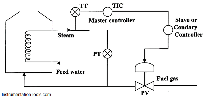
Cascade means two controllers is series. One of them is the Master or Primary and the second is the secondary of slave controller. The output of the secondary controller operates the final control element.
Loop explanation: The output of the temperature transmitter goes as measurement signal to the TIC which is the master controller. Similarly the output of pressure transmitter goes as measurement signal to the PlC which is the secondary controller.
The output of TIC comes at set point to PlC which is turn operates the valve. The reqd. temp. is set on theTIC.
Use of cascade system:
Cascade loops are invariably installed to prevent outside disturbances from entering the process. The conventional single controller as shown in the diagram cannot responds to a change in the fuel gas pressure until its effect is felt by the process temperature sensor. In other words an error in the detected temperature has to develop before corrective action can be taken. The cascade loop in contrast responds immediately correcting for the effect of pressure change, before it could influence the process temperature. The improvement in control quality due to cascading is a function of relative speeds and time lags.
A slow primary (Master) variable and a secondary (Slave) variable which responds quickly to disturbances represent a desirable combination for this type of control. If the slave can respond quickly to fast disturbances then these will not be allowed to enter the process and thereby will not upset the control of primary (master) variable. It can be said that use of cascade control on heat transfer equipment contributes to fast recovery from load changes or other disturbances.
