For the block diagram of the input module shown, Section #1 represents the
____ and #2 the ____.
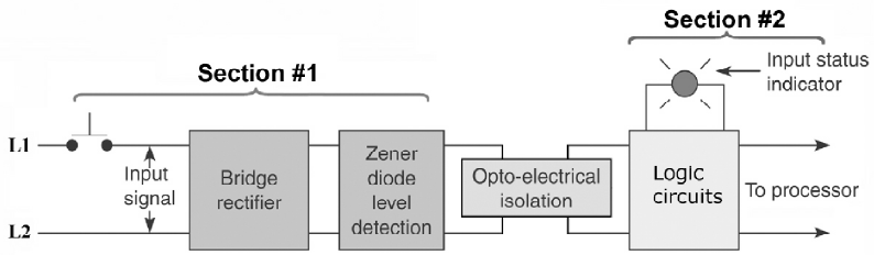
A. AC, DC.
B. DC, AC.
C. power, logic.
D. logic, power.
Show Answer
Answer: C
Share your understanding of this question with the correct explanation.c