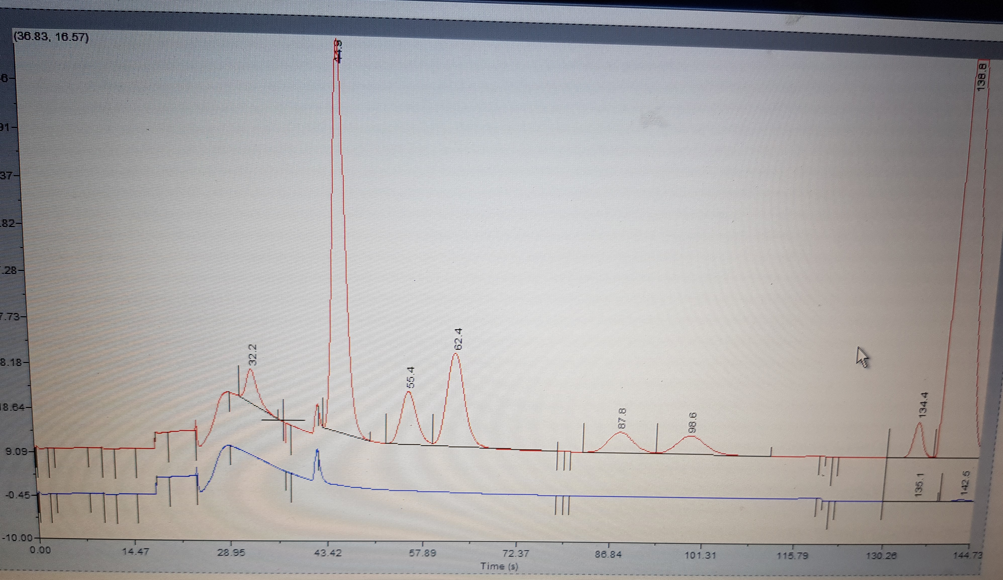
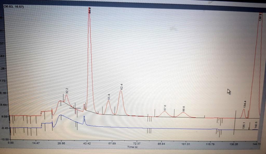
Please I need your help for adjust/tuning GC DANIEL 370XA with MON2020 software using chromatogram (attached), in the chromatogram you can see irregular curves (baseline no horizontal) from 0 to 72.37 seg, I was trying to adjust changing open/close valve times (TIMED EVENTS) but C6+ analysis decrease from 0.056 to 0.00%, the actual total time for analysis is 240 seg, changing open/close valve times the total time can be increased from 240 to 280 seg can be this problem?
somebody have someone procedure for tuning/adjust GC DANIEL 370XA?
Downward drift for a few minutes is normal after installing a new column
Increase the oven temperature to close to the maximum continuous operating temperature for the column. Maintain the temperature until flat baseline is observed. If the detector signal does not drop in 10 minutes, immediately cool the column and check for leaks.
Unequilibrated detector
Allow sufficient time for temperature equilibration of the detector.
Downward drift is frequently due to the “back-out” of contaminants from the detector or other parts of the GC
Clean out contamination.
Upward drift
Possible cause
Suggestions
Damage to the stationary phase of the GC column
Determine the cause of the damage. It may be due to impurities in the carrier gas or to excessive temperatures. Replace column.
Drift in gas flow rates
Clean or replace flow or pressure regulator(s). Adjust pressure.
Noise
Possible cause
Suggestions
The column may be inserted too far into the flame of an FID, NPD or FPD detector
Reinstall the column. Be sure to insert the column into the detector exactly the correct distance specified in the instrument manual.
An air leak can result in noise in ECD and TCD detectors
Eliminate the leak.
Incorrect combustion gases or flow rates can generate nois in FID, NPD or FPD detectors.
Be sure yuor gases are the proper grade, as well as clean and dry. Reset the flow rates of the gases to their proper values.
Contaminated injector
Clean injector. Replace inlet liner, septa and selas.
Contaminated column
Bake out the column. Cut off first 10 cm of column. If it does not help, replace the column.
Defective detector
Clean and/or replace parts as necessary.
Defective detector board
Consult GC manufacturer.
Offset
Possible cause
Suggestions
Line voltage changes
Monitor line voltage for correlation with offset. If correlation is found, install voltage regulator or ensure stable power supply.
Poor electrical changes
Check electrical connections. Tighten any loose connections. Clean any dirty or corroded connections.
Contaminated injector
Clean injector. Replace inlet liner, septa and selas.
Contaminated column
Bake out the column. Cut off first 10 cm of column. If it does not help, replace the column.
Column inserted too fat into the flame of FID, NPD or FPD detectors
Reinstall the column. Be sure to insert the column into the detector exactly the correct distance specified in the instrument manual.
Contaminated detector
Clean the detector if possible.
Spiking
Possible cause
Suggestions
Electrical disturbances entering the chromatograph through power cables, even shielded cables
Try to correlate spikes with events in equipment near the chromatograph. Periodicity is often a clue. Turn off equipment or move it. If necessary, install a voltage regulator.
Wander
Possible cause
Suggestions
Baseline wandering may be caused by changes in environmental conditions such as temperature or line voltage
Try to correlate the wandering with environmental parameters. If a correlation is observed, you will know what to do.
Inadequate temperature control Check if variations can be correlated with changes in the baseline position.
Measure detector temperature.
Wandering while using isothermal conditions may be due to contaminated carrier gas
Change the carrier gas or the gas purification traps.
Contaminated injector
Clean injector. Replace inlet liner, glass wool and seals.
Contaminated column
Bake out the column. Cut off first 10 cm of column. If it does not help, replace the column.
Check the concentration and stability of the sample.
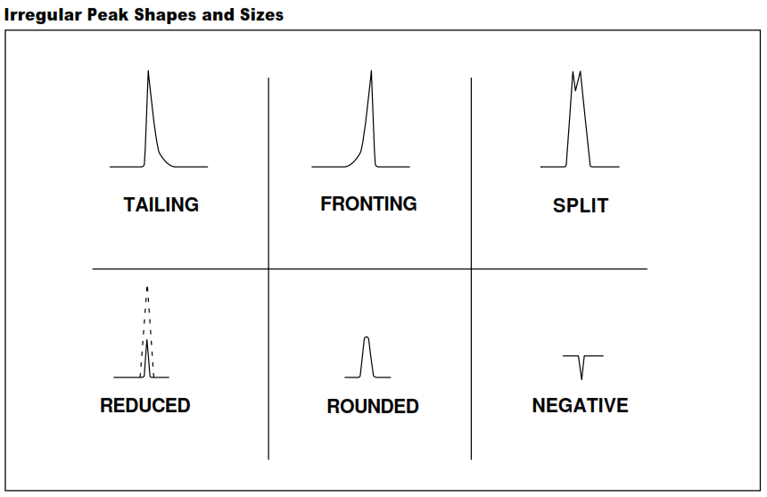
Flattened top peaks
Possible cause
Suggestions
Detector overload. The broad peaks may have a rounded top or even valleys in the top.
Reduce sample volume, dilute with solvent or use higher split ratio.
Overload of the signal processing electronics. The peaks are clipped with flat tops.
Attenuate detector output or reduce sample amount (see above).
Fronting peaks
Fronting peaks are usually the result of column overloading. In this case, the effect should be a function of injection volume. Solutions include reducing the injection volume or using a column with greatr capacity. Columns with larger diameter or thicker stationary phase coatings generally have larger sample capacities, however, resolution may be reduced.
Ghost peaks
Possible cause
Suggestions
Remmants of previous samples in the inlet or column. Ghost peaks due to remmants are most likely to occur when increasing inlet or column temperatures.
Increase the final temperature and lengthen the run time to allow for complete elution of previous samples. If ghost peaks continue to occur, clean the inlet. Condition the column at temperature higher than has been used but lower than the maximum continuous operation temperature for the column. Cut 10 cm off the inlet end of the column and/orreverese it before reconditioning it. If it does not help, replace the column.
Backflash may cause remmants. Backflash refers to vapours from the sample which expand to exceed the volume of the injector liner. These vapours may come in contact with colder spots, such as the septum and gas inlets of the injector. Less volatile components may condense. These condensates may vaporize later and interfere with subsequent analyses, sometimes producing “ghost peaks”.
* Use septum purge
Lower injection volume
Enlarge injector liner
Optimize injector temperature
Use pressure pulsed program|
|Bleed from the septum or fragments of the septum lodged in the inlet or liner.|Clean the inlet. Replace the inlet liner, glass wool and seals.|
Irreproducible peak heights or areas
Possible cause
Suggestions
Inconsistent injection
Develop a reproducible injection technique. Use autosampler.
Distorted peak shapes can adversely affect quantitative determinations
Correct any problems that result in the distortion of peak shape. See Peak shape problems.
Set-up right parameters in your chromatography software.
Sample compound has greater thermal conductivity than the carrier gas and you are using a TCD or µTCD detector
If possible, change carrier gas. Otherwise there is not a solution.
Detector overload in element-specific detectors such as ECD, NPD, FPD, etc., can produce both positive and negative peaks
Have the compound of interest arrive at the detector at a different time from the solvent or other compounds in high concentration. H2 produces negative peaks with TCD (µTCD) and helium carrier gas.
Dirty ECD detector can give negative peak after a positive one
Clean or replace the ECD detector.
No peaks at all
Possible cause
Suggestions
Defective syringe
Try a new or proven syringe.
“Blown” septum or massive leaks at the inlet
Find and fix leaks.
Problems with carrier gas flow
Adjust gas flow. Check the column flow ath the column outlet by immersion to methanol.
Broken column or column installed in the wrong way
Replace or reinstall the column.
The detector is not functioning or not connected to the recorder or integrator.
Ensure that detector is working properly. E.g.: Is the flame in a FID on? Check connection to the output device.
Selective sensitivity loss
Possible cause
Suggestions
Contamination of column and/or liner can lead to loss of sensitivity for active compounds
Clean liner. Bake out the column or replace it.
Injector leaks reduce the peak height of the most volatile components of a sample more than less volatile
Find and fix any leaks.
Initial column temperature too high for splitless injection which can prevent refocusing of sample. This affects the more volatile components most.
Initial column temperature should be below the boiling point of the solvent. Decrease the initial column temperature or use less volatile solvent.
Inlet descrimination. Injector temperature is too low. Later eluting and less volatile compounds have low response.
Increase injection temperature.
Split peaks
Possible peaks
Suggestions
Fluctuations in column temperature
Repair temperature control system
Mixed sample solvent for splitless or on-column injections
Use single solvent
When using injection techniques that require " solvent effect " refocusing such as splitless injectiion, the solvent must form a compact, continuous flooded zone in the column. If the solvent does not wet the stationary phase sufficiently as might be the case for methanol used with a nonpolarstationary phase, the solvent flooded zone may be several meters long and not of uniform thickness. This will result in broad and distorted peaks because the solutes will not be refocused into a narrow band near the beginning of the column.
Installing a retention gap (5 meters of uncoated but deactivated column) ahead of the crhomatographic column may reduce or eliminate this problem.
Tailing peaks
Possible cause
Suggestions
Contaminated or active injector liner, seal or column
Clean or replace injector liner. Do not use glass wool in the liner. If necessary, replace the column.
Dead volume due to poorly installed liner or column.
Confirm by injecting inert peak (methane). If it tails, column is not properly installed. Reinstall liner and column as necessary.
Ragged column end
Score the tubing lightly with a ceramic scoring wafer or sapphire scriber before breaking it. Examine the end using magnifying glass. If the break is not clean and the end square, cut the column again. Point the end down while breaking it and while installing a nut and ferrule to prevent fragments from entering the column. Reinstall the column.
A bad match between the polarities of the stationary phase and the solvent
Change the stationaryphase. Usually polar analytes tail on no-polar columns, or dirty columns.
A cold region in the sample flow path
Remove any cold zones in the flow path
Debris in the liner or column
Clean or replace the liner. Cut 10 cm off the end of the column and reinstall it.
Injection takes too long.
Improve injection technique.
Split ration is too low
Increase split ratio to at least 20:1
Overloading the inlet
Decrease the sample volume or dilute sample
Some types of compounds such as alcoholic amines, primary and secondary amines and carboxylic acids tend to tail.
Try a more polar column. Make a derivative of the dsample.
Retention time shifts
Possible cause
Suggestions
Change in column temperature
Check GC oven temperature
Change in gas flow rate (linear velocity)
Inject a detectable unretained sample such as methane to determine the linear gas velocity. Adjust gas pressure or flow to obtain proper values for your analytical method.
Leak in the injector
Check the septum first. Change, if necessary. Find the leak and fix it.
Change of solvent
Use the same solvent for standards and samples.
Contaminated column
Bake out the column. Cut 10 cm off the end of the column. If necessary, replace the column.
Loss of resolution
Possible cause
Suggestions
Damage to stationary phase of column
Replace the column. This is usually indicated by excessive column bleeding or peak tailing.
Injector problems
Check for leaks, inapropriate temperature, split ration, purge time, dirty liner, glass wool in liner.
Large increase in sample concentration
* Dilute sample
Inject less
Use higher split ratio|
Broad solvent front
Possible cause
Suggestions
Bad column installation
Reinstall column
Injector leak
Find and fix leak
Injection volume too large
Decrease sample size or dilute it
Injection temperature too low
Increase injection temperature so the entire sample is vaporized “instantly”. An injection temperature higher than the temperature limit of the column will not damage the column.
Split ratio is too low
Increase split ratio.
Column temperature too low
Increase column temperature (ba careful on maximum column temperature limit). Use a lower boiling solvent.
Initial column temperature too high for splitless injection
Decrease the initial column temperature. Use a less volatile solvent so the initial column temperature is below the solvent boiling point.
Purge time too long (splitless injection)
Use a shorter purge valve close time.
Rapid column performance degradation
Possible cause
Suggestions
Broken column
Replace column. Avoid damaging the polyimide coating on the column. Avoide temperatures above maximu column temperature limit. Avoid abrasion of the column. Remember, even if the column does not break immediately, when protective coating is damaged the column may possibly break spontaneously later.
Column too hot for too long
Replace the column. Stay below limits specified for the column.
Exposure to oxygen, particularly at elevated temperatures
Find and fix any lieaks. Be sure carrier gas is sufficiently pure.
Chemical damage due to inorganic acids or bases
Keep inorganic acids or bases out of column. Neutralize samples.
Contamination of the column with nonvolatile materials
Prevent nonvolatile materials from getting into column. For expample, use a guard column.
Too much thanks, but I forget a detail, when I change the gas sample for Helium pure (another bottle of same carrier gas) the chromatogram from 0.0 to 43.42 seg. no change (Red line is for Natural Gas Standart and Blue line is for Helium pure), so am thinking the problem is contamination because with Helium pure the chromatogram should be horizontal line without peaks. how to can solve this problem?, I already did a 12-hour running analisys wit helium pure but the chromatogram no change.
We too face the basline issue once when we change the Helium cylinder supplier.
The quality of helium gas is degrated and started the baseline problem in GC.
Make sure to check the helium gas cylinder.
Aslo is this issue started after changing the helium gas cylinder? then replace this cylinder with new one and check again. if you have sufficient helium in old cylinder (for few hours only) then us the same for confirmation of this issue.
Sometimes you need to clean the six port valve also.
Please confirm from O.E.M. to avoid unnecessary trail and error tests. Because there is a high chance of GC analysis distrubance with these trails.
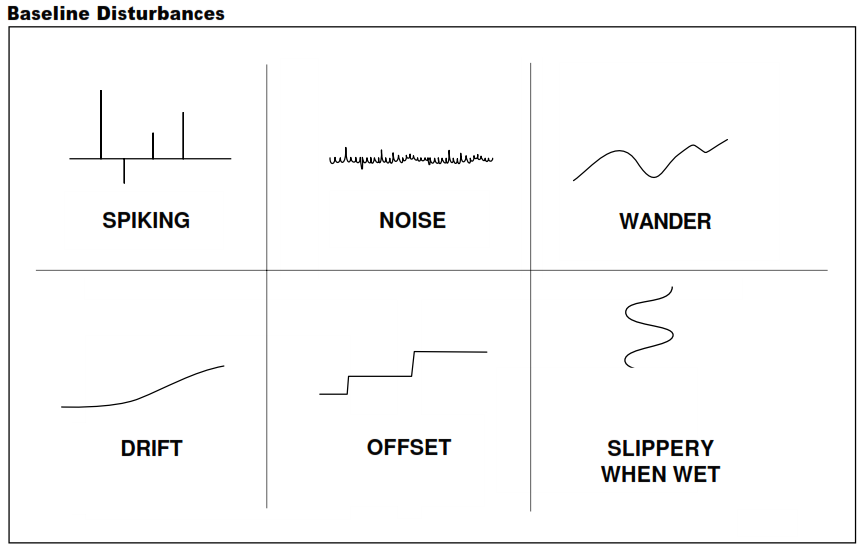
 Baseline problems could be divided into 5 categories: drift, noise, offset, spiking and wander.