Recognize hand-off-automatic switches on a schematic diagram.
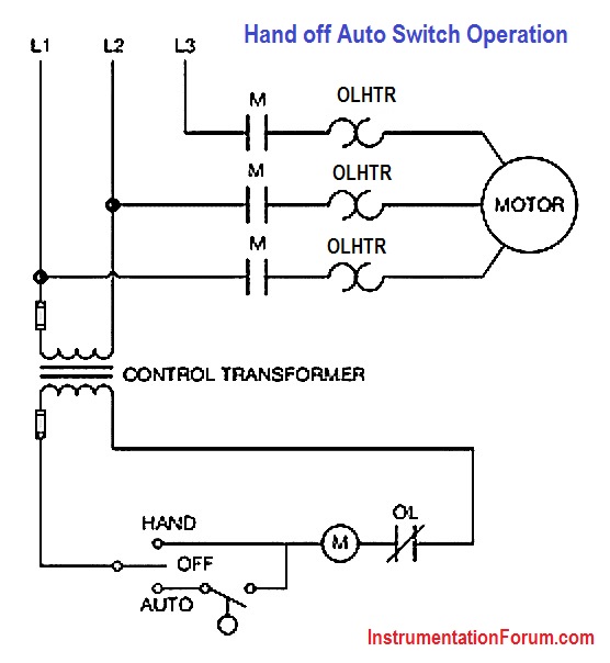
Hand-off-automatic controls are used to permit an operator to select between automatic or manual operation of a motor. The circuit shown in below Figure permits a motor to be operated by a float switch or to be run manually. The switch is shown as a single-pole double- throw switch with a center Off position.
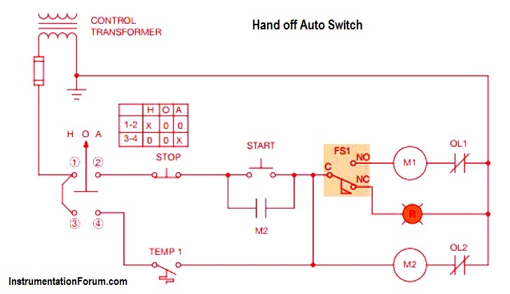
Another symbol for a hand-off-automatic switch is shown in Below Figure. This switch is shown to contain two separate sets of contacts. One set is labeled 1-2 and the other is labeled 3-4. The switch chart indicates that when the switch is in the Off position, there is no connection between any of the contacts. When set in the Hand position, connection is made between terminals 1 and 2. When set in the Automatic position, connection is made between terminals 3 and 4. This circuit is the control for a large fan that pulls air through a building. The motor in this example is water cooled: it requires a flow of cooling water when running. Starter M1 controls the fan motor, and starter M2 controls a pump used to circulate water through the motor. Flow switch FS1 detects the flow of water to insure that the fan motor cannot run if there is no flow of cooling water. A warning lamp indicates that there is no flow of water when the circuit is energized.
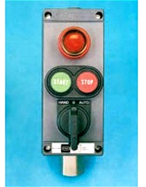
When the hand-off-automatic switch is set in the Hand position, connection is made between terminals 1 and 2. This permits the motor to be controlled by a start-stop push-button station. In this mode, the fan will run continuously until the Stop button is pressed. When the HOA switch is placed in the Auto position, a thermostat controls the action of the fan. A combination push-button station with a hand-off-automatic switch and pilot lamp is shown in above Figure.
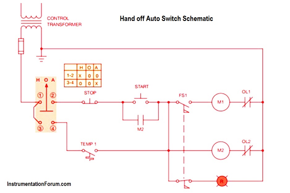
The flow switch shown in second Figure employs two separate contacts, one normally open and the other normally closed. The dashed line indicates that the two switches are mechanically connected. When one switch changes position the other switch changes position also. If a flow switch with two separate switches cannot be obtained, it is possible to use a single-pole connected together. This forms a common point for both switches and could be used as the common terminal for a flow switch that contains a single-pole double-throw switch, below Figure. Although the circuit shown in below Figure looks different than the circuit in second Figure, electrically they are the same and will operate in the same manner.