In our day-to-day life, we have become quite familiar by witnessing several fire accidents as they occur in manufacturing industries, organizations, companies, shopping complexes, and residential places due to different reasons & become the headings of leading News papers. These fire accidents usually cause property or money loss and lead to severe injuries or casualties.
To avoid such fire accidents and minimize the loss due to them, development of a good security / protection system remains a better option. Such a system can be developed by designing a better prototype in the form of a few latest electronics projects using heat sensors or heat detectors. These sensor based projects include firefighting robots to extinguish the fire, automatic heat detector circuit to avoid the occurrence of fire accidents.
Heat Detector

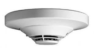
Heat Detector (Thermistor)
Heat detector can be defined as an element or device that detects changes in heat or fire. If any heat (change in heat that exceeds the limits of heat sensor ratings) is sensed by the heat sensor, the heat sensor generates a signal for alerting or activating a security or protection system to extinguish or avoid the fire accidents. There are different types of heat sensors, which are classified based on different criteria such as the amount of heat withstanding capacity, nature of heat sensing capacity, and so on. Furthermore, the heat sensors are classified into different types that include analog heat sensors and digital heat sensors.
Heat Detector Circuit
Heat detector can sense the heat (change in heat according to the features of heat detector used). But, a circuit is to be designed for activating an alarm system to indicate fire or heat change and for alerting the security or protection system. Heat detector circuit can be designed using heat sensor.
These heat detectors are mainly classified into two types based on their operation and they are “rate of rise heat detectors” and “fixed temperature heat detectors”.
Rate-of-Rise Heat Detectors
These heat detectors operates irrespective of the starting temperature, for the rapid rise in element temperature ranging from 12° to 15°F (6.7° to 8.3°C) increase per minute. If the threshold of these types of heat detectors is fixed, then these can be operated at a low temperature fire condition. This heat detector consists of two heat-sensitive thermocouples or thermistors. One thermocouple is used to monitor the heat transferred by convection or radiation. The other thermocouple responds to the ambient temperature. Heat detector will respond whenever the first thermocouple temperature increases relative to the other thermocouple.

Rate-of-Rise Heat Detectors
A Rate-of-rise heat detector doesn’t respond to low energy release rates of deliberately developing fires. Combination detectors add a fixed temperature element that can be used for detecting slowly developing fires. This element ultimately responds whenever the fixed temperature element reaches the design threshold.
Fixed Temperature Heat Detectors
Fixed Temperature Heat Detectors
This is most frequently used heat detector. Whenever the temperature or heat changes, then the eutectic point of heat sensitive eutectic alloy changes from solid to liquid and thus fixed temperature detectors operate. Generally, for electrically connected fixed temperature point is 136.4 degree F or 58 degree C.
The Principle of Operation of Heat Detector Circuit
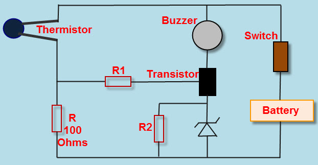
A simple heat detector circuit is shown in the figure that can be used as a heat sensor. In this heat detector circuit diagram, a potential divider circuit is formed with a series connection of thermistor and 100 Ohms resistance. If (Negative temperature Coefficient) N.T.C type thermistor is used, then the resistance of thermistor decreases after heating. Thus, more current flows through the potential divider circuit formed by thermistor and 100 Ohms resistance. Hence, more voltage appears at the junction of thermistor and resistor.
Heat Detector Circuit
Let us consider thermistor having 110 Ohms, and after heating its resistance value becomes 90 Ohms. Then, as per potential divider circuit which is pervasive concept namely voltage divider: the voltage across one resistor and the ratio of that resistor’s value and the sum of resistances times the voltage across the series combination are equal. The input-output relationship for this heat detector circuit system, takes the form of a ratio of the output voltage to the input voltage which is given by the voltage divider concept in this particular concept.
Finally, the output voltage is applied to NPN transistor shown in the circuit through a resistor. A zener diode is used to maintain emitter voltage at 4.7 volts, which can be used comparatively. If the base voltage is greater than the emitter voltage, then the transistor starts conduction. This is because as the transistor gets more than 4.7V base Voltage and a buzzer are connected to complete the heat detector circuit which is used for producing sound.
Heat Detector Circuit Using SCR and LED
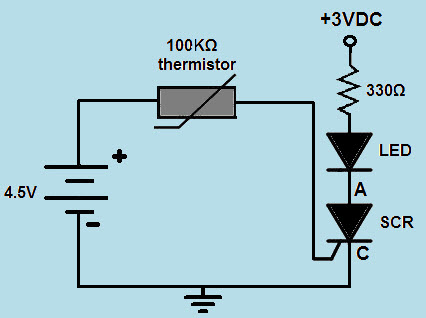
The heat detector circuit is designed using thermistor, but instead of using transistor and buzzer, here SCR and LED are used. The SCR is connected in series with the LED. Here LED is used as an alerting element. The RED LED connected in the circuit is switched to indicating the significant change in heat sensed by the thermistor.
Heat Detector Circuit using SCR and LED
Generally, thermistor offers very high resistance (approximately equal to its rated value of 100KΩ) at room temperature. Due to this very high resistance, practically no current will flow. Hence, no triggering pulse is given to the SCR gate terminal. But, if a significant amount of heat is sensed by the thermistor, then the resistance of a thermistor significantly decreases. Thus, sufficient amount of current flows through the circuit and the gate terminal of SCR is triggered. Therefore, the LED connected in series with the SCR is turned ON as an alert indicating the change in heat.
Similarly, we can practically implement electronics projects to develop different heat detector circuits. Here, primarily we discussed about heat detector circuit with buzzer alarm activated using a transistor; we can use SCR instead of transistor. In this way, the combination of alerting elements and activating elements can be changed to practically implement different types of heat detector circuits. This heat detector circuit can be modified by changing the output element buzzer or LED with some other loads. For example, we can use a specific heat detector circuit with certain limits which will turn on a fan or cooler or air conditioner by detecting change in heat.
Practical Application of Heat Detector Circuit
Firefighting robot controlled using RF transmitter and RF receiver is a simple example electronics project, which is a practical application of heat detector. The circuit consists of heat detector (thermistor) that is connected to the microcontroller of the receiver block which is interfaced with robotic vehicle. Under normal room temperature, the robot’s heat detector will not give any signal to the microcontroller and thus pump remains off.
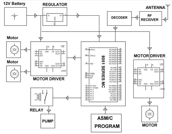
If once heat detector detects any considerable change, then it sends signal to the microcontroller. Further, the microcontroller sends a signal to the pump through a relay to activate it and extinguish the fire (if any). Thus, heat detector can be used in real time embedded systems based project firefighting robotic vehicle and industrial temperature controller project.
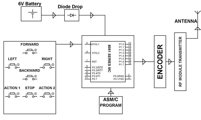
This robotic vehicle can be controlled using RF technology consisting of RF transmitter and RF receiver. RF transmitter can be used by the controller to send commands to robotic vehicle to move into the specific direction: left or right or forward or backward and also to start or stop the robotic vehicle. RF receiver connected to the robotic vehicle receives these commands. These commands are fed to the microcontroller and thus the microcontroller controls the motors direction accordingly through a motor driver IC.
We hope that from this article you might have got very brief but quite useful & practical information about heat detector circuits and their principle of operation. If you are aware of any other practical applications of heat detectors, then share your technical knowledge by posting in the comments section below to improve the knowledge of other readers and also to encourage others to share their views and doubts regarding the final year engineering project works.