Another installation method for level measurement using DP level transmitter is by utilizing diaphragm seal plus capillary tube. To determine the calibrated range for DP level transmitter in this installation, the fill fluid within the capillary shall be taken into account in calculation since the fill fluid also creates hydrostatic force exerting both DP level transmitter ports.
The density of fill fluid must be known, the information could be obtained from vendor catalog.
An example below describes the calculation in determining the calibrated range for DP level transmitter with capillary tube.
DP Level Transmitter Calculations
Given:
Process fluid density (ρP) = 950 kg/m3
Fill fluid density (ρF) = 1050 kg/m3
Maximum Level to be measured from process tap (h) = 4 m
Height Difference between two taps (h2) = 5 m
Gravitational acceleration = 9.81 m/s2
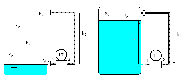
0 mA = dP at level min (left image)
∆P at min level
= P1 – P2
= Pv – (Pv + ρF . g . h2 )
= – ρF . g . h
= – 1050 . 9.81 . 5
= – 51502 Pa
= – 515 mbar
24mA = dP at level max (right image)
∆P at max level
= P1 – P2
= (Pv + ρP . g . h ) – (Pv + ρF . g . h2 )
= (ρP . g . h) – (ρF . g . h2)
= (950 . 9.81 . 4) – (1050 . 9.81 . 5)
= – 14224 Pa
= – 142 mbar
Note that the transmitter mounting elevation can be disregard if both capillaries are filled with the same fill fluid. The transmitter elevation becomes a concern if only one leg is attached while the other port is exposed to atmosphere.
The use of diaphragm seal in level measurement is subject to zero suppression or zero elevation.