Incremental Encoder Working Principle
The incremental encoder, sometimes called a relative encoder, is simpler in design than the absolute encoder. It consists of two tracks and two sensors whose outputs are called channels A and B.
As the shaft rotates, pulse trains occur on these channels at a frequency proportional to the shaft speed, and the phase relationship between the signals yields the direction of rotation.
The code disk pattern and output signals A and B are illustrated in Figure 5. By counting the number of pulses and knowing the resolution of the disk, the angular motion can be measured.
The A and B channels are used to determine the direction of rotation by assessing which channels “leads” the other.
The signals from the two channels are a 1/4 cycle out of phase with each other and are known as quadrature signals. Often a third output channel, called INDEX, yields one pulse per revolution, which is useful in counting full revolutions. It is also useful as a reference to define a home base or zero position.
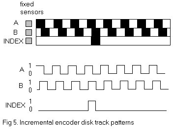
Figure 5 illustrates two separate tracks for the A and B channels, but a more common configuration uses a single track with the A and B sensors offset a 1/4 cycle on the track to yield the same signal pattern. A single-track code disk is simpler and cheaper to manufacture.
The quadrature signals A and B can be decoded to yield the direction of rotation as hown in Figure 6. Decoding transitions of A and B by using sequential logic circuits in different ways can provide three different resolutions of the output pulses: 1X, 2X, 4X. 1X resolution only provides a single pulse for each cycle in one of the signals A or B, 4X resolution provides a pulse at every edge transition in the two signals A and B providing four times the 1X resolution.
The direction of rotation(clockwise or counter-clockwise) is determined by the level of one signal during an edge transition of the second signal.
For example, in the 1X mode, A=![]() with B =1 implies a clockwise pulse, and B=
with B =1 implies a clockwise pulse, and B=![]() with A=1 implies a counter-clockwise pulse. If we only had a single output channel A or B, it would be impossible to determine the direction of rotation.
with A=1 implies a counter-clockwise pulse. If we only had a single output channel A or B, it would be impossible to determine the direction of rotation.
Furthermore, shaft jitter around an edge transition in the single signal would result in erroneous pulses.
