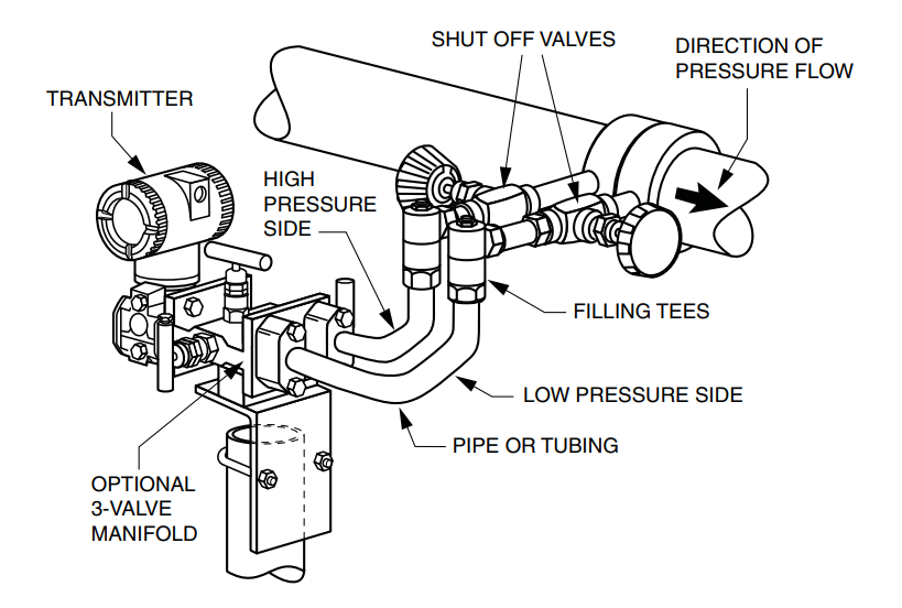
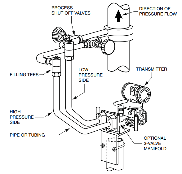
The below figures show typical installations with horizontal and vertical process pipes for flow transmitter.
The transmitters are shown below the level of the pressure connections at the pipe (usual arrangement, except for gas flow without a seal liquid), and with filling tees in the lines to the transmitter (for a seal liquid).
If the process fluid being measured must not come in contact with the transmitter, the transmitter lines must be filled with a suitable seal liquid (see procedure in next section). In such a case, the transmitter must be mounted below the level of the pressure connections at the pipe. With steam flow, the lines are filled with water to protect the transmitter from the hot steam.
The seal liquid (or water) is added to the lines through the filling tees. To prevent unequal heads on the transmitter, the tees must be at the same elevation and the transmitter must be mounted vertically (as shown). If a seal liquid is not required, elbows can be used in place of the tees.
Tighten drain plugs and optional vent screws to 20 N⋅m (15 lb⋅ft).
Tighten the four process connector bolts to a torque of 61 N⋅m (45 lb⋅ft). Note that the low and high pressure sides of the transmitter are identified by an L-H marking on the side of the sensor above the warning label.
With medium viscosity seal liquids and/or long transmitter lines, larger valve sizes should be used.
Example of Horizontal Process Line Installation
Example of Vertical Process Line Installation
Filling System with Seal Liquid
If the process fluid being measured must not come in contact with the transmitter, the transmitter lines must be filled with a suitable seal liquid. The procedure to do this is as follows:
-
If the transmitter is in service, follow the procedure for “Taking a Differential Pressure Transmitter Out of Operation”.
-
Close both process shutoff valves.
-
Open all three valves on the 3-valve manifold.
-
Partially open the vent screws on the transmitter until all air has been forced out of the transmitter body and lines. Close the vent screws.
-
Refill the tee connections. Replace the plugs and close the bypass valve. Check for leaks.
-
Follow the procedure for “Putting a Differential Pressure Transmitter Into Operation.
Source: Foxboro