- In Wheatstone bridge connecting leads might induce error, to measure resistance less than 10^ -3 ohms we make use of Kelvin double bridge.
- An essential phenomenon includes creating voltage divider across Ry.
6 Likes
Provide derivation if possible.
1 Like
For sure.
3 Likes
When the resistance to be measured is of the order of magnitude of bridge contact and lead resistance, a modified form of Wheatstone’s bridge, the Kelvins Bridge theory is employed.
Kelvins Bridge theory is a modification of Wheatstone’s bridge and is used to measure values of resistance below 1 Ω. In low resistance measurement, the resistance of the leads connecting the unknown resistance to the terminal of the bridge circuit may affect the measurement.
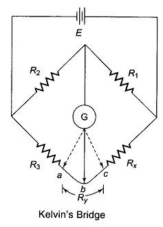
Consider the circuit in Fig. 11.10, where R represents the resistance of the connecting leads from R3 to Rx (unknown resistance). The galvanometer can be connected either to point c or to point a. When it is connected to point a, the resistance Ry, of the connecting lead is added to the unknown resistance Rx, resulting in too high indication for Rx.
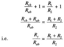
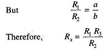
When the connection is made to point c, R3, is added to the bridge arm R3 and resulting measurement of Rx is lower than the actual value, because now the actual value of R3 is higher than its nominal value by the resistance Ry. If the galvanometer is connected to point b, in between points c and a, in such a way that the ratio of the resistance from c to b and that from a to b equals the ratio of resistances R1 and R2, then
and the usual balance equations for the bridge give the relationship
Therefore
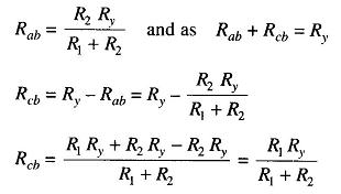
Substituting for Rab and Rcb in Eq. (11.7), we have
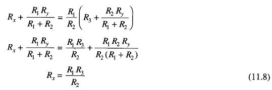
Equation (11.8) is the usual Wheatstone’s balance equation and it indicates that the effect of the resistance of the connecting leads from point a to point c has been eliminated by connecting the galvanometer to an intermediate position, b.
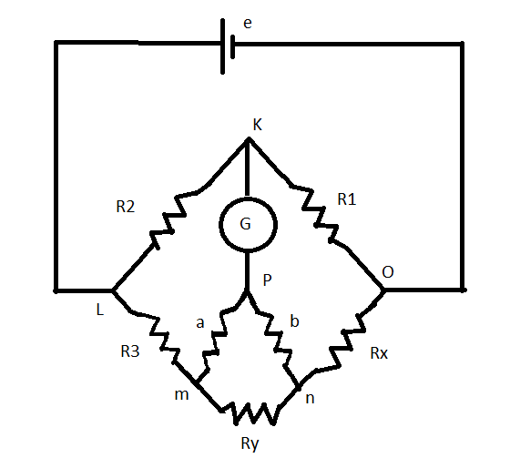
The above principle forms the basis of the construction of Kelvin’s Double Bridge, popularly known as Kelvin’s Bridge. It is a Double bridge because it incorporates a second set of ratio arms. Figure 11.11 shows a schematic diagram of Kelvin’s double bridge.
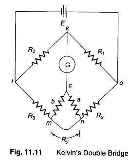
The second set of arms, a and b, connect the galvanometer to a point c at the appropriate potential between m and n connection, i.e. Ry. The ratio of the resistances of arms a and b is the same as the ratio of R1 and R2. The galvanometer indication is zero when the potentials at k and c are equal.
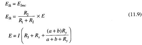
Substituting for E in Eq.(11.9),
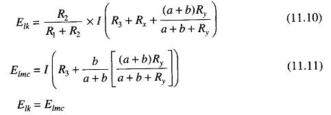
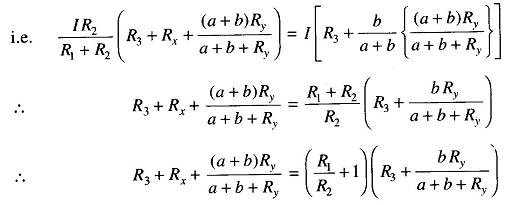
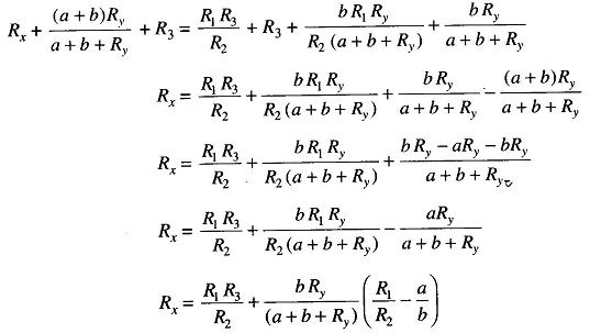
This is the usual equation for Kelvins Bridge theory. It indicates that the resistance of the connecting lead has no effect on the measurement, provided that the ratios of the resistances of the two sets of ratio arms are equal. In a typical Kelvins Bridge theory the range of a resistance covered is 1 — 0.00001 Ω (10 μohm) with an accuracy of ± 0.05% to ± 0.2%.
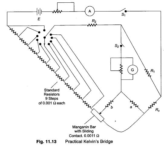
Practical Kelvins Double Bridge:
Figure 11.13 shows a commercial Kelvin’s bridge capable of measuring resistances from 10 — 0.00001 Ω.
Contact potential drops in the circuit may cause large errors. This effect is reduced by varying a standard resistance consisting of nine steps of 0.001 Ω each, plus a calibrated manganin bar of 0.0011 Ω with a sliding contact. When both contacts are switched to select the suitable value of standard resistance, the voltage drop between the ratio arm connection points is changed, but the total resistance around the battery circuit is unchanged.
This arrangement places any contact resistance in series with the relatively high resistance value of the ratio arms, rendering the contact resistance effect negligible. The ratio R1/R2 is selected (as given in Fig. 11.13) such that a relatively large part of the standard resistance is used and hence Rx, is determined to the largest possible number of significant figures. Therefore, measurement accuracy improves.
5 Likes