Orifice plates are really hard to install. To get a good velocity profile, the mechanical specification for meter tube, the orifice flanges or fitting the differential pressure sensing taps, the upstream and downstream piping requirements must be adhere to the standard. But don’t worry, velocity profiles are only pretty pictures in engineering textbooks
Orifice Plates and holders
Orifice plates are usually installed between special flanges in a horizontal pipe run. The flanges are thicker than normal to accommodate two small bore tapings for connection to a DP cell.
The plate is positioned concentrically within the flange bolt circle with the tap protruding near the top of flanges. The tab has a hole and the orifice plates must have information engraved to indicate the correct upstream / downstream orientation.
Orifice taps
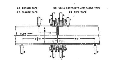
There are 4 common arrangements of pressure taps:
-
Flange taps: Flange taps are the most popular because the distance from the orifice plate is precisely controlled
-
vena contracta: located to obtain the maximum differential pressure across the orifice
-
corner taps L located at each side of the orifice plate and are good for pressure measurement in pipes less than 50 mm diameter
-
Pipe taps: To measure the permanent loss of pressure across an orifice
Special shaped orifices
For special applications there are several special-shaped orifices. The quadrant edge (quarter cicle) orifice is used at reynold numbers below which the square edge concentric orifice coefficient becomes too nonlinear. A conic entrance orifice can also be used for a similar range of reynolds number
Eccentric, segmental, and annular orifice are special devices to take care of dirty fluids and two-phase flows, but give bad accuracies (2%)
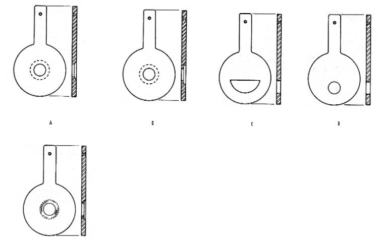
Fig 2. A.Bore and Bevel orifice B. Bore and counter bore C. Segmental D. Eccentric. E. Quarter-Round
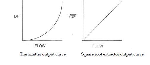
Relationship between differential pressure and flow
When a differential pressure cell is used to transmit a flow measurement the output of the transmitter is not linear. Therefore, in many flow measurement installation, a square root extractor is fitted to the output of a differential pressure transmitter
DP flow can be derived from the Bernoulli equation
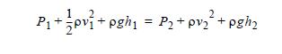
By assuming density is constant, the continuity equation can be written as
A1V1 = A2V2
The equation can be abbreviated as follows:
-
Cancel the potential energy in Bernoulli equation (assume the pipe is level )
-
Solve V1 and V2 using the continuity equation
-
Substitude V1 in term of V2
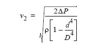
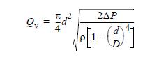
Then the volumetric flow equation can be obtained by multiplying by the cross sectional area of the throat,
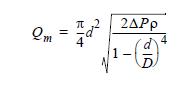
if the mass flow is required, multiply both sides by flowing density
References:
- API MPMS 14.3.1&2 Orifice plate
- Daniel orifice catalogue
- Rosemount DP flow technical notes