A PLC (i.e. Programmable Logic Controller ) is a device that was invented to replace the necessary sequential relay circuits for machine control.
The PLC works by looking at its inputs and depending upon their state, turning on/off its outputs. The user enters a program, usually via software, that gives the desired results.
PLC Study Material
PLC Example :
• Let’s assume that when a switch turns on we want to turn a solenoid on for 5 seconds and then turn it off regardless of how long the switch is on for.
• We can do this with a simple external timer. But what if the process included 10 switches and solenoids? We would need 10 external timers. What if the process also needed to count how many times the switches individually turned on? We need a lot of external counters.
PLC - need :
• The bigger the process the more is need for a PLC.
• Simply program the PLC to count its inputs and turn the solenoids on for the specified time.
• The primary reason for designing PLC was eliminating the large cost involved in replacing the complicated relay based machine control systems.
Inside PLC :
• The PLC mainly consists of :
- A CPU,
- Memory areas, and
- Appropriate circuits to receive input/output data.
• We can actually consider the PLC to be a box full of hundreds or thousands of separate relays, counters, timers and data storage locations.
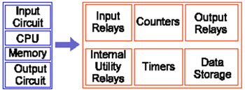
• INPUT RELAYS-(contacts) : These are connected to the outside world. They physically exist and receive signals from switches, sensors, etc. Typically they are not relays but rather they are transistors.
• INTERNAL UTILITY RELAYS-(contacts) : These do not receive signals from the outside world nor do they physically exist. They are simulated relays and are what enables a PLC to eliminate external relays. There are also some special relays that are dedicated to performing only one task. Some are always on while some are always off. Some are on only once during power-on and are typically used for initializing data that was stored.
• COUNTERS : These again do not physically exist. They are simulated counters and they can be programmed to count pulses. Typically these counters can count up, down or both up and down.
• TIMERS : These also do not physically exist. They come in many varieties and increments. The most common type is an on-delay type. Others include off-delay and both retentive and non-retentive types. Increments vary from 1ms through 1s.
• OUTPUT RELAYS-(coils): These are connected to the outside world. They physically exist and send on/off signals to solenoids, lights, etc. They can be transistors, relays, or triacs depending upon the model chosen.
• DATA STORAGE : Typically there are registers assigned to simply store data. They are usually used as temporary storage for math or data manipulation. They can also typically be used to store data when power is removed from the PLC. Upon power-up they will still have the same contents as before power was removed.
PLC Operation :
• A PLC works by continually scanning a program. We can think of this scan cycle as consisting of 3 important steps.
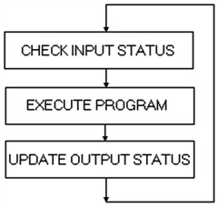
• Step 1-CHECK INPUT STATUS : First the PLC takes a look at each input to determine if it is on or off. In other words, is the sensor connected to the first input on? How about the second input? How about the third… It records this data into its memory to be used during the next step.
• Step 2-EXECUTE PROGRAM : Next the PLC executes program one instruction at a time. Maybe program said that if the first input was on then it should turn on the first output. Since it already knows which inputs are on/off from the previous step it will be able to decide whether the first output should be turned on based on the state of the first input. It will store the execution results for use later during the next step.
• Step 3-UPDATE OUTPUT STATUS : Finally the PLC updates the status of the outputs. It updates the outputs based on which inputs were on during the first step and the results of executing your program during the second step. Based on the example in step 2 it would now turn on the first output because the first input was on and your program said to turn on the first output when this condition is true. After the third step the PLC goes back to step one and repeats the steps continuously. One scan time is defined as the time it takes to execute the 3 steps listed above.
PLC - Response :
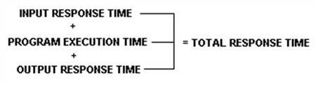
• The total response time of the PLC is a fact we have to consider when purchasing a PLC.
• PLC takes a certain amount of time to react to changes. In many applications speed is not a concern, in others though…
PLC – Response Time Concern :
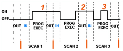
• Input 1 is not seen until Scan 2.
• Input 2 is not seen until Scan 3.
• Input 3 never seen by PLC.
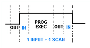
• To avoid this we say that the input should be ON for at least 1 input delay time + one scan time .
• But what if it was not possible for the input to be on this long? Then the plc doesn’t see the input turn on.
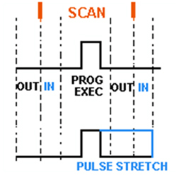
Pulse Stretch Function :
• This function extends the length of the input signal until the plc looks at the inputs during the next scan.( i.e. it stretches the duration of the pulse.)
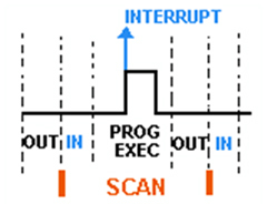
Interrupt Function :
• This function interrupts the scan to process a special routine i.e. As soon as the input turns on, regardless of where the scan currently is, the PLC immediately stops what its doing and executes an interrupt routine.
• An interrupt routine can be thought of as a mini program outside of the main program. After its done executing the interrupt routine, it goes back to the point it left off at and continues on with the normal scan process.
Relays :
• We understand how the PLC processes inputs, outputs, and the actual program.
• Now lets see How a relay actually works . After all, the main purpose of a PLC is to replace “real-world” relays.
• We can think of a relay as an electromagnetic switch.
• Apply a voltage to the coil and a magnetic field is generated. This magnetic field sucks the contacts of the relay in, causing them to make a connection.
• These contacts can be considered to be a switch. They allow current to flow between 2 points thereby closing the circuit.
Relays – a real example :
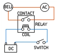
• Here we simply turn on a bell whenever a switch is closed.
• We have 3 real-world parts : A switch , a relay and a bell . Whenever the switch closes we apply a current to a bell causing it to sound.
Replacing Relays :
• Lets use a PLC in place of the relay.
• The first thing that’s necessary is to create what’s called a Ladder Diagram .
• We have to create one of these because, unfortunately, a PLC doesn’t understand a schematic diagram it only recognizes code.
• Most PLCs have software which convert ladder diagrams into code.
Ladder Diagram :
• First Step : Translate all of the items we’re using into symbols the PLC understands.
• Second step : We must tell the PLC where everything is located. In other words we have to give all the devices an address.
• Final step : We have to convert the schematic into a logical sequence of events.
First Step :
• The PLC doesn’t understand terms like switch, relay, bell, etc.
• It prefers input, output, coil, contact, etc.
• It doesn’t care what the actual input or output device actually is. It only cares that its an input or an output.
• First we replace the battery with a symbol. This symbol is common to all ladder diagrams. We draw what are called bus bars .
• These simply look like two vertical bars. One on each side of the diagram. Think of the left one as being + voltage and the right one as being ground. Further think of the current (logic) flow as being from left to right.
• Next we give the inputs a symbol. In this basic example we have one real world input. (i.e. the switch).
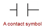
• We give the input that the switch will be connected to the symbol shown below. This symbol can also be used as the contact of a relay .
• Next we give the outputs a symbol. In this example we use one output (i.e. the bell).
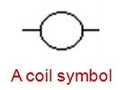
• We give the output that the bell will be physically connected to the symbol shown below. This symbol is used as the coil of a relay.
• The AC supply is an external supply so we don’t put it in our ladder. The PLC only cares about which output it turns on and not what’s physically connected to it.
Second Step :
• We must tell the PLC where everything is located. In other words we have to give all the devices an address.
• Where is the switch going to be physically connected to the PLC? How about the bell? We start with a blank road map in the PLCs town and give each item an address.
• Could you find your friends if you didn’t know their address? You know they live in the same town but which house? The plc town has a lot of houses (inputs and outputs) but we have to figure out who lives where (what device is connected where).
• We’ll get further into the addressing scheme later. The PLC manufacturers each do it a different way! For now let’s say that our input will be called “0000”. The output will be called “500”.
Final Step :
• Convert the schematic into a logical sequence of events.
• The program we’re going to write tells the PLC what to do when certain events take place.
• In our example we have to tell the plc what to do when the operator turns on the switch.
• Final converted diagram.
• We eliminated the real world relay from needing a symbol.
Basic Instructions :
Load :
• The load(LD) instruction is a normally open contact . It is sometimes also called examine if on ( XIO ).(as in examine the input to see if its physically on). The symbol for a load instruction is shown below.
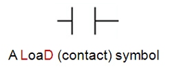
• This is used when an input signal is needed to be present for the symbol to turn on.
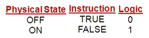
• When the physical input is on we can say that the instruction is True.
• We examine the input for an on signal. If the input is physically on then the symbol is on.
• An on condition is also referred to as a logic 1 state.
Load Bar :
• The Load bar instruction is a normally closed contact . It is sometimes also called LoaDNot or examine if closed( XIC )(as in examine the input to see if its physically closed) The symbol for a loadbar instruction is shown below.
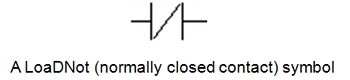
• This is used when an input signal does not need to be present for the symbol to turn on.
• When the physical input is off we can say that the instruction is True .
• We examine the input for an off signal. If the input is physically off then the symbol is on.
• With most PLCs this instruction( Load or Loadbar ) MUST be the first symbol on the left of the ladder.
Out :
• The Out instruction is sometimes also called an Output Energize instruction . The output instruction is like a relay coil . Its symbol looks as shown below.
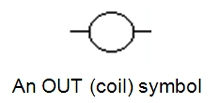
• When there is a path of True instructions preceding this on the ladder rung, it will also be True.
• When the instruction is True it is physically ON .
• We can think of this instruction as a normally open output.
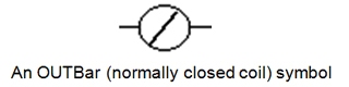
Out Bar :
• The Outbar instruction is sometimes also called an OutNot instruction.
• The Outbar instruction is like a normally closed relay coil . Its symbol looks like that shown below.
A Simple Example :
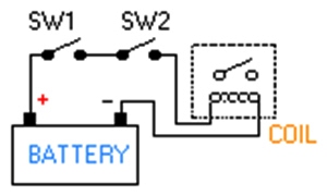
• In the above circuit, the coil will be energized when there is a closed loop between the + and - terminals of the battery.
• We can simulate this same circuit with a ladder diagram.
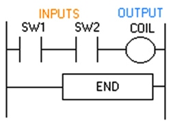
• A ladder diagram consists of individual rungs just like on a real ladder.
• Each rung must contain one or more inputs and one or more outputs.
• The first instruction on a rung must always be an input instruction and the last instruction on a rung should always be an output (or its equivalent).
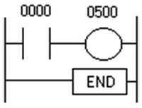
• Notice in this simple one rung ladder diagram we have recreated the external circuit above with a ladder diagram.
• Here we used the Load and Out instructions.
• Some manufacturers require that every ladder diagram include an END instruction on the last rung. Some PLCs also require an ENDH instruction on the rung after the END rung.
• Next we’ll trace the registers
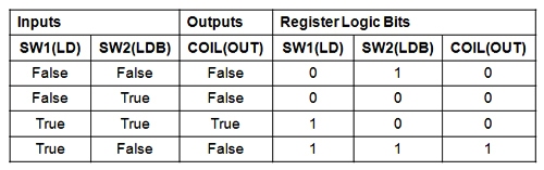
PLC Registers :
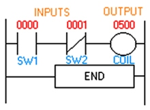
• In Previous example change switch 2 (SW2) to a normally closed symbol (loadbar instruction).
• SW1 will be physically OFF and SW2 will be physically ON initially . The ladder diagram now looks like this :
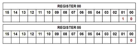
• We gave each symbol (or instruction) an address.
• This address sets aside a certain storage area in the PLCs data files so that the status of the instruction (i.e. true/false) can be stored.
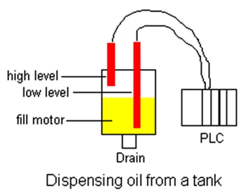
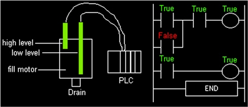
A Level Application :
• We are controlling lubricating oil being dispensed from a tank.
• This is possible by using two sensors.
• We put one near the bottom and one near the top, as shown in the picture.
Here, we want the fill motor to pump lubricating oil into the tank until the high level sensor turns on. At that point we want to turn off the motor until the level falls below the low level sensor. Then we should turn on the fill motor and repeat the process.
Here we have a need for 3 I/O (i.e. Inputs/Outputs) :
• 2 are inputs (the sensors) and 1 is an output (the fill motor).
• Both of our inputs will be NC (normally closed) fiber-optic level sensors. When they are NOT immersed in liquid they will be ON. When they are immersed in liquid they will be OFF.
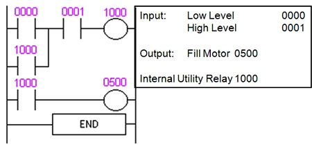
Program Scan :
• Initially the tank is empty. Therefore, input 0000 is TRUE and input 0001 is also TRUE.
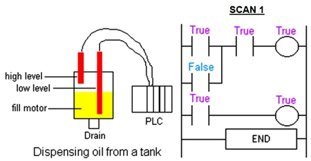
• Gradually the tank fills because 500(fill motor) is on.
• After 100 scans the oil level rises above the low level sensor and it becomes open. (i.e. FALSE).
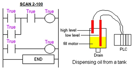
• Even when the low level sensor is false there is still a path of true logic from left to right. This is why we used an internal relay. Relay 1000 is latching the output (500) on. It will stay this way until there is no true logic path from left to right.(i.e. when 0001 becomes false).
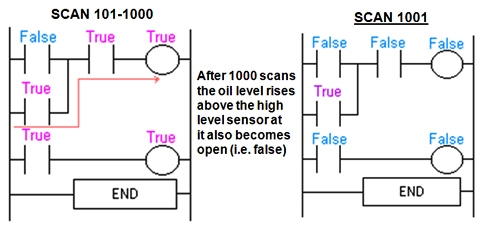
• Since there is no more true logic path, output 500 is no longer energized (true) and therefore the motor turns off.
• Even though the high level sensor became true there still is NO continuous true logic path and therefore coil 1000 remains false!.
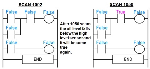
• After 2000 scans the oil level falls below the low level sensor and it will also become true again.
• At this point the logic will appear the same as SCAN 1 above and the logic will repeat as illustrated above.
Latch Instruction :
• The latching instructions let us use momentary switches and program the plc so that when we push one the output turns on and when we push another the output turns off.
• Picture the remote control for your TV. It has a button for ON and another for OFF :
- When I push the ON button the TV turns on.
- When I push the OFF button the TV turns off.
• I don’t have to keep pushing the ON button to keep the TV on. This would be the function of a latching instruction.
• The latch instruction is often called a SET or OTL (output latch).
• The unlatch instruction is often called a RES (reset), OUT (output unlatch) or RST (reset). The diagram below shows how to use them in a program.
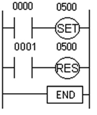
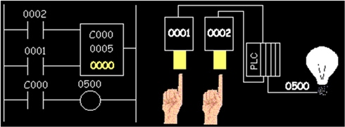
Here we are using 2 momentary push button switches. One is physically connected to input 0000 while the other is physically connected to input 0001. When the operator pushes switch 0000 the instruction “set 0500” will become true and output 0500 physically turns on. Even after the operator stops pushing the switch, the output (0500) will remain on. It is latched on. The only way to turn off output 0500 is turn on input 0001. This will cause the instruction “res 0500” to become true thereby unlatching or resetting output 0500.
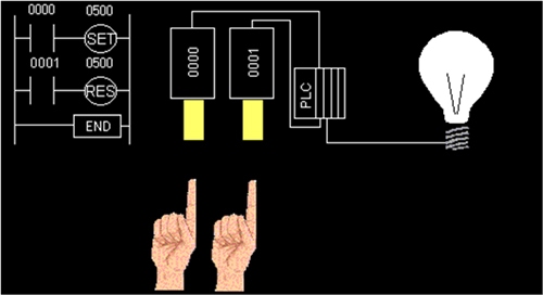
• What would happen if input 0000 and 0001 both turn on at the exact same time.
• Will output 0500 be latched or unlatched?
• To answer this question we have to think about the scanning sequence. The ladder is always scanned from top to bottom, left to right.
• The first thing in the scan is to physically look at the inputs.
• 0000 and 0001 are both physically on.
• Next the PLC executes the program.
• Starting from the top left, input 0000 is true therefore it should set 0500.
• Next it goes to the next rung and since input 0001 is true it should reset 0500.
• The last thing it said was to reset 0500. Therefore on the last part of the scan when it updates the outputs it will keep 0500 off. (i.e. reset 0500).
Counters :
• A counter is a simple device intended to do one simple thing - count.
• There are up-counters (they only count up 1,2,3…). These are called CTU,(count up) CNT,C, or CTR.
• There are down counters (they only count down 9,8,7,…). These are typically called CTD (count down).
To use Counters we must know 3 things :
• Where the pulses that we want to count are coming from. Typically this is from one of the inputs.(a sensor connected to input 0000 for example).
• How many pulses we want to count before we react. Let’s count 5 widgets before we box them, for example.
• When/how we will reset the counter so it can count again. After we count 5 widgets lets reset the counter , for example.
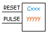
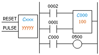
• In this counter we need 2 inputs :
- One goes before the reset line. When this input turns on the current (accumulated) count value will return to zero.
- The second input is the address where the pulses we are counting are coming from.
• Cxxx is the name of the counter. If we want to call it counter 000 then we would put “C000” here.
• yyyyy is the number of pulses we want to count before doing something.
Timers :
• TIMER : It is an instruction that waits a set amount of time before doing something.
• Type of Timers : On-Delay Timer and Off-Delay Timer.
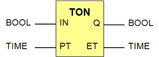
On-Delay Timer :
• Simply “delays turning on”.
• After sensor (input) turns ON, wait x-seconds before activating a solenoid valve(output).
• This is the most common timer. It is often called TON (timer on-delay), TIM (timer) or TMR (timer).
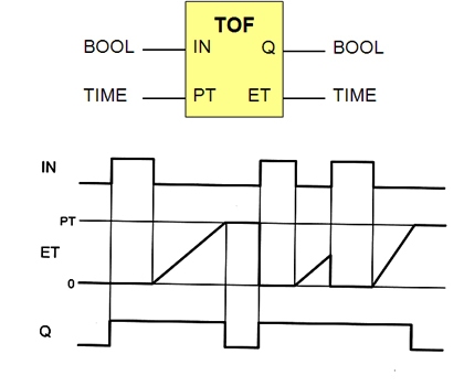
Off-Delay Timer :
• Simply “delays turning off”.
• After sensor (input) sees a target it turn on a solenoid (output).
• When the sensor no longer sees the target it hold the solenoid on for x-seconds before turning it off.
• It is called a TOF (timer off-delay).
Need to know 2 things :
• What will enable the timer :
- Typically this is one of the inputs,(a sensor connected to input 0000 for example).
• How long we want to delay before we react.
- Let’s wait 5 seconds before we turn on a solenoid, for example.
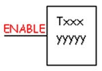
On-Delay Timer :
• Txxx : Timer Name.
• When the enable input is ON the timer starts to tick.
• When it ticks yyyyy (the preset value) times, it will turn on its contacts that we will use later in the program.
Timer in Ladder Diagram :
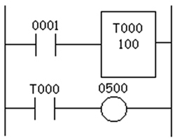
• Wait for input 0001 to turn on.
• Timer T000 (a 100ms increment timer) starts ticking. It will tick 100 times. Each tick (increment) is 100ms so the timer will be a 10000ms (i.e. 10 second) timer.
• 100ticks X 100ms = 10,000ms .
• When 10 seconds have elapsed, the T000 contacts close and 500 turns on.
• When input 0001 turns off (false) the timer T000 will reset back to 0 causing its contacts to turn off (become false) thereby making output 500 turn back off.
One Shot :
• A one-shot is used to make something happen for ONLY 1 SCAN .
• Most manufacturers have one-shots that react to an off to on transition and a different type that reacts to an on to off transition.
• Some names for the instructions could be DIFU/DIFD (differentiate up/down), SOTU/SOTD (single output up/down), OSR (one-shot rising) and others.
Master Controls :
• Master controls can be thought of as “emergency stop switches” .
• An emergency stop switch typically is a big red button on a machine that will shut it off in cases of emergency.
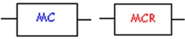
• The master control instruction typically is used in pairs with a master control reset.
• It is commonly abbreviated as MC/MCR (master control/master control reset).
• Timers should not be used inside the MC/MCR block.
MCR in Ladder Diagram :
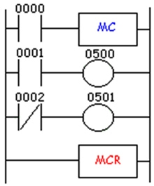
• In this example, rungs 2 and 3 are only executed when input 0000 is on (true).
• If input 0000 is not true the plc pretends that the logic between the MC and MCR instructions does not exist.
Shift Registers :
• To store many previous events and act upon them later.
• We use a register or group of registers to form a train of bits (cars) to store the previous on/off status. Each new change in status gets stored in the first bit and the remaining bits get shifted down the train.
• SFT (ShiFT), BSL (Bit Shift Left), SFR (Shift Forward Register).
• BSR (Bit Shift Right) and SFRN (Shift Forward Register Not).
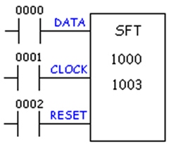
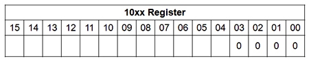
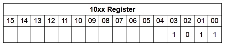
Symbol needs 3 inputs and has some data inside the symbol : 1000: First Bit, 1003 : Last Bit.
• Data : The data input gathers the true/false statuses that will be shifted down the train. When the data input is true the first bit (car) in the register (train) will be a 1. This data is only entered into the register (train) on the rising edge of the clock input.
• Clock : The clock input tells the shift register to “do its thing”. On the rising edge of this input, the shift register shifts the data one location over inside the register and enters the status of the data input into the first bit. On each rising edge of this input the process will repeat.
• Reset : The reset input does just what it says. It clears all the bits inside the register we’re using to 0.
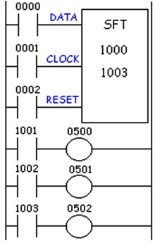
Shift Registers - Application :
• Imagine an ice-cream cone machine. We have 4 steps :
- First we verify the cone is not broken.
- Next we put ice cream inside the cone.(turn on output 500).
- Next we add peanuts.(turn on output 501).
- Finally we add sprinkles.(turn on output 502).
• If the cone is broken we obviously don’t want to add ice cream and the other items. Therefore we have to track the bad cone down our process line so that we can tell the machine not to add each item.
• We use a sensor to look at the bottom of the cone (input 0000). If its on then the cone is perfect and if its off then the cone is broken.
• An encoder tracks the cone going down the conveyor. (input 0001). A push button on the machine will clear the register. (input 0002).
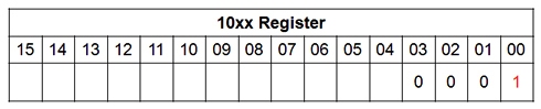
A good cone comes in front of the sensor (input 0000). The sensor (data input) turns on. 1000 will not turn on until the rising edge of the encoder (input 0001). Finally the encoder now generates a pulse and the status of the data input (cone sensor input 0000) is transferred to bit 1000. The register now looks like :
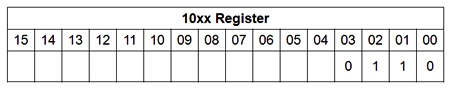
As the conveying system moves on, another cone comes in front of the sensor. This time it’s a broken cone and the sensor remains off. Now the encoder generates another pulse. The old status of bit 1000 is transferred to bit 1001. The old status of 1001 shifts to 1002. The old status of 1002 shifts to 1003. And the new status of the data input (cone sensor) is transferred to bit 1000. The register now looks like :
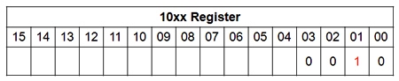
Since the register shows that 1001 is now on, the ladder says that output 0500 will turn on and ice cream is put in the cone. As the conveying system continues to move on, another cone comes in front of the sensor. This time it’s a good cone and the sensor turns on. Now the encoder generates another pulse. The old status of bit 1000 is transferred to bit 1001. The old status of 1001 shifts to 1002. The old status of 1002 shifts to 1003. And the new status of the data input (cone sensor) is transferred to bit 1000. The register now looks like :
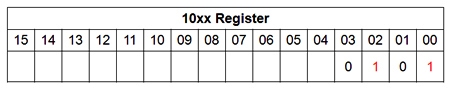
Since the register shows that 1002 is now on the ladder says that output 0501 will turn on and peanuts are put on the cone. Since 1001 now holds the status of a broken cone, 500 remains off in the ladder above and no ice-cream is inserted into this cone.
As the conveying system continues to move on, another cone comes in front of the sensor. This time it’s also a good cone and the sensor turns on. Now the encoder generates another pulse.
- The old status of bit 1000 is transferred to bit 1001.
- The old status of 1001 shifts to 1002.
- The old status of 1002 shifts to 1003.
- And the new status of the data input(cone sensor) is transferred to bit 1000. The register now looks like :
• Since the register shows that 1003 is now on the ladder says that output 0502 will turn on and sprinkles are put on the cone.
• Since 1002 now holds the status of a broken cone, 501 remains off in the ladder above and no peanuts are put onto this cone.
• Since the register shows that 1001 is now on the ladder says that output 0500 will turn on and ice cream is put in that cone.
As the conveying system continues to move on, another cone comes in front of the sensor. This time it’s another broken cone and the sensor turns off. Now the encoder generates another pulse.
The old status of bit 1000 is transferred to bit 1001.
The old status of 1001 shifts to 1002.
The old status of 1002 shifts to 1003.
And the new status of the data input (cone sensor) is transferred to bit 1000.
The register now looks like :
Notice that the status of our first cone has disappeared.
• The shift register is most commonly used in conveyor systems, labeling or bottling applications, etc.
Programming Languages :
• IEC 61131-3 defines FIVE programming languages for PLC.
• The languages can be mixed in any way within a PLC project.
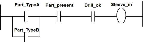
• Machining process involved in Valve Production :
- Two sensors are used to establish whether a work piece with correctly drilled holes is available at the machining position.
- If the valve to be machined is of type A or type B (set via two selector switches).
- The cylinder advances and presses the sleeve in to the drilled hole.
Ladder Diagram (LD) :
• Graphical Programming language derived from the circuit diagram of directly wired relay controls.
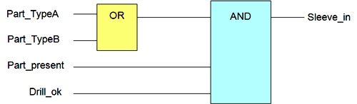
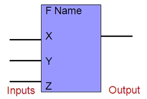
Functional Block Diagram (FBD) :
• Functions and function blocks are represented graphically and interconnected into networks.
• Originates from Logic diagrams.
Instruction List (IL) :
• Textual Assembler-type language.
• Formulated from control instructions consisting of an operator and an operand.
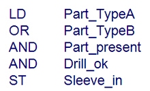
Structured Text (ST) :
• Structured text is high-level language based on Pascal, which consists of expressions and instructions.
Sequential Functional Chart (SFC) :
• Language resource for the structuring of sequence oriented control programs. The elements of SFC are steps, transitions, alternative and parallel branching.
Common Elements of Programming Languages :
• Resources of a PLC :
-> Inputs, outputs and the memory.
-> Directly addressed variables.
• Variables and data types :
-> Representation of data.
-> Data types.
-> Variable declaration.
-> Initialization.
• Program :
-> Functions.
-> Function blocks.
Inputs, outputs and memory :
• Designation of resources :
-> Inputs I.
-> Outputs Q.
-> Memory M.
• Data types :
-> BOOL (X) 1 bit.
-> BYTE (B) 8 bit.
-> WORD (W) 16 bit.
• IX, QX, MX, IB, QB, MB, IW, QW, MW.
• Multiple resources :
-> I1 Input 1.
-> I15 Input 15.
-> QW3 Output Word 3.
-> MB5 Memory Byte 5.
• Directly addressed variables :
-> Resource in control program addressed directly.
-> Prefixed with the sign %.
-> %I12 – Input bit 12, %QB8 – Output byte 8.
Variables and Data Types :
• Representation of Numerical Data :
-> Integers: 12, -8, 123_456, +751.
-> Floating point: 0.123_4, -12.0, -8.0.
-> Numbers to base 2: 2#1101_0011.
-> Numbers to base 8: 8#323.
-> Numbers to base 16: 16#D3.
-> Boolean: 0, 1.
• Representation of Time Data :
-> Time duration: T#18ms, TIME#18ms, t#3.5s.
-> Date: D#2008-04-21, DATE#2008-04-21.
-> Time of day: TOD#13:18:42.55.
-> Date and Time: DT#2008-04-21:13:18:42.55.
• Representation of Strings :
->‘B’ character.
-> ‘warning’ string.
• Data Types :
-> BOOL
-> SINT, INT, DINT, UINT
-> REAL
-> TIME
-> STRING
-> BYTE
-> WORD
• Controller program constructed into individual organization units :
-> Configuration.
-> Resources.
-> Programs.
-> Function blocks.
-> Functions.
• All variables have specific position.
• All variable declaration starts with a keyword, which designate position of variable and end with keyword END_VAR
VAR
Temp : INT;
Hand : BOOL;
END_VAR
• Keywords for variable declaration :
-> Input variables VAR_INPUT
-> Output variables VAR_OUTPUT
-> In/Output variables VAR_IN_OUT
-> Local variables VAR
-> Global variables VAR_GLOBAL
-> External variables VAR_EXTERN
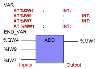
• Keyword AT is used to assign variables to the inputs and outputs of the controller.
VAR
Stop_button AT %I2 : BOOL;
Temperature AT %IW3 : BOOL;
END_VAR
PROGRAM :
• Program for a controller is divided into individual organization units at the programming level :
-> Programs.
-> Function blocks.
-> Functions.
Functions :
• Function are software modules which, when invoked provide exactly one result.
• E.g. Addition of INT values or logic OR.
• Standard Functions :
-> AND, OR, XOR, NOT.
-> SHL, SHR, ROR, ROL.
-> GT, GE, EQ, LE, LT, NE.
-> ADD, MUL, SUB, DIV, MOVE.
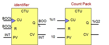
Function Blocks :
• Function blocks are software modules, which supply one or several result parameters.
• One important characteristic is possibility of instantiation.
• To use, a copy or instance must be created.
• The status information of the function block copy remains intact from one processing to the next.
• Example : Counters, Timers.
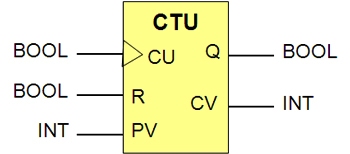
• CTU : incremental counter.
Standard Function Blocks :
• CTU – Incremental counter.
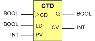
• CTD – Decremental counter.
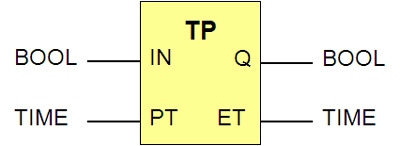
• TP – Pulse.
• TON – Switch-ON delay signal.
• TOF – Switch-OFF signal delay.
• R_TRIG – Edge detection: rising edge.
• F_TRIG – Edge detection: falling edge.
Programs :
• Consists of any language elements.
• Constructs necessary instructions to achieve the desired machine or process behavior by PLC.
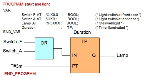
• Stairwell Light Control Program :
-> The stairwell light is switched ON for 3 min, if one of the two light switches on the apartment door or the front door is activated.
Timers :
• IEC 61131-3 defines 3 types of timer function blocks :
-> TP Pulse Timing.
-> TON On-delay timing.
-> TOF Off-delay timing.
• Time duration is specified by means of a defined character format :
-> T#2h15m, T#20s.
-> T#10m25s, t#3h_40m_20s.
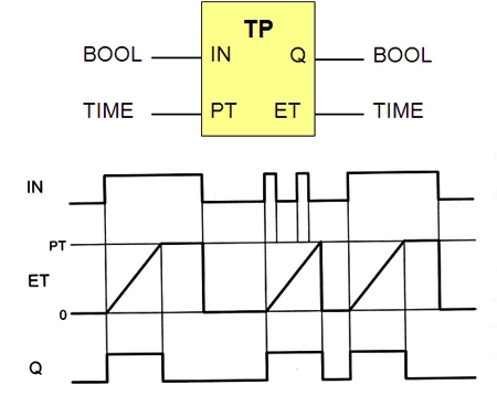
Timers – TP Pulse Timer :
• TP is started by a shorter or longer 1-signal at input IN. A 1-signal now applies at output Q for the time specified at its input PT (preset time).
• The output signal Q has a fixed duration.
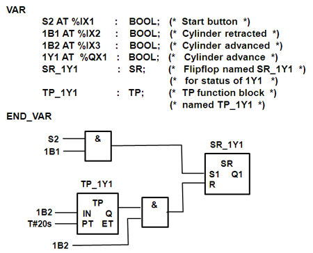
TP Pulse Timer Example :
• Pressing of the start button S2 is to cause the piston of a cylinder to advance. This mechanism is used to clamp workpieces.
• When the piston advance fully, it is to remain in this position for 20 seconds.
• The cylinder then returns to its initial position.
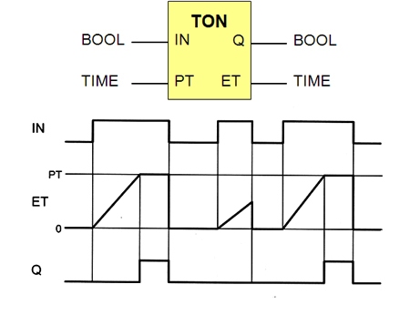
Timers – Switch-On signal delay :
• TON is used to generate switch ON signal delays.
• After the start via a 1-signal at input IN, output Q does not assume value 1 until the time specified at input PT has expired, and retains this until input signal IN returns to 0.
• If the duration of input signal IN is shorter than the PT, the value of output remains at 0.
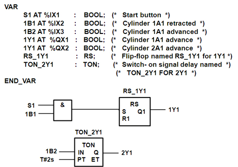
TON Example :
• Cylinder 1A1 extends, if start button S1 is actuated.
• Once this has been extended for 2s, a second cylinder 2A1 move to its forward end position.
• Sensors 1B1 and 1B2 indicates the retracted and the forward end positions of cylinder 1A1.
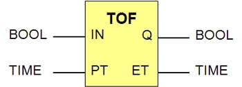
Timers – Switch-Off signal delay :
• TOF is used to generate switch OFF signal delays.
• Timer start via a 1-signal at input IN, at the same time, output Q assume value 1.
• After the input signal IN has reverted to the value 0, the output remains at 1 for the duration PT and does not return to 0 until it expired.
Incremental counter CTU :
• Counter is set at the initial value 0 by a signal at reset input R.
• The value in the counter is incremented by 1 with each positive edge at counter input CU (count up).
• As soon as current value is equal to or greater than the preset value, the output value assumes value 1. Prior to reaching this value Q = 0.
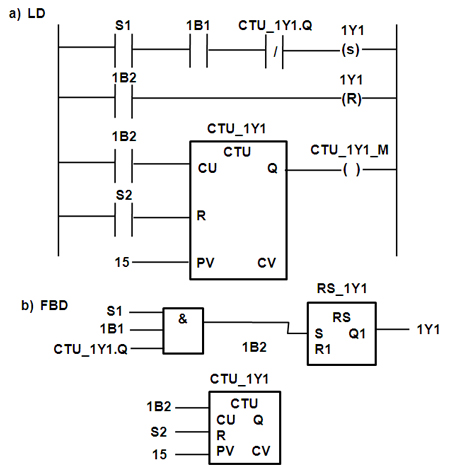
CTU example :
• Parts are to be ejected from a gravity-feed magazine via a cylinder.
• If Push button S1 is actuated, the cylinder is to advance, eject a workpiece and then retract again.
• 15 parts are to be ejected in this way. When 15 parts have been ejected, it should no longer be possible to trigger a cylinder movement via push button S1. First the counter must be reset by actuating push button S2.
Decremental counter CTD :
• The decremental counter with preselect value PV is loaded with a 1-signal at input LD (load).
• During normal operation, each positive edge at input CD (count down) reduces the counter reading.
• Output Q of function block CTD is 0, until the counter reading CV becomes less than or = 0.
CTD example :
• A cylinder is moved via a valve 1Y1.
• The position of cylinder is signaled via the sensors 1B1 (retracted) and 1B2 (extended).
• The cylinder is to advance, if push button S1 is pressed.
• When 10 strokes have been executed this way, lamp H1 is illuminated and the counter has expired.
• The counter must be re-loaded with the preset value, before any cylinder movements can be executed further. This is affected by means of actuating push button S2.
Automation Control Systems :
Automation control systems :
• These control systems are used in manufacturing plants of all types, and some other applications that you may not have considered.
• The control systems are built around special devices, designed to operate industrial machines, and processes. We call these devices Programmable Logic Controllers (PLC) and Programmable Automation Controllers (PAC).
PLC and PAC Systems :
• PLCs were introduced in the early 1970s. The term “PAC”, was developed to differentiate those older systems from today’s much more powerful, and flexible devices.
• An analogy can be made between the VHS video tape, and a DVD. Both systems allow viewers to record TV programs for viewing at a latter time, but the DVD also can also be used to record music, data, and more.
• PLCs were designed to control machinery. PACs can be used for machine control, process, motion control, and other applications.
• We will use the term PLC generically to refer to both PLCs, and PACs.
• This section will explore the various components that comprise a PLC system.
Basic Components of a PLC System :
There are five basic components in a PLC system :
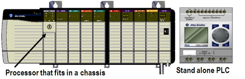
• The PLC processor, or controller.
• I/O (Input /Output) modules.
• Chassis or backplane.
• Power supply.
• Programming software that runs in a PC.
In addition to these 5, most PLCs also have : A network interface. Let’s look at each in more detail…
Processor, Controller, or CPU :
• Stores the control program and data in its memory.
• Reads the status of connected input devices.
• Executes the control program.
• Commands connected outputs to change state based on program execution.
- For example : Turn a light on, start a fan, adjust a speed, or temperature.
• Comes in various physical forms.
I/O Modules :
• Physically connect to field devices.
• Input modules convert electrical signals coming in from input field devices such as pushbuttons, to electrical signals that the PLC can understand.
• Output modules take information coming from the PLC and convert it to electrical signals the output field devices can understand, such as a motor starter, or a hydraulic solenoid valve.
• I/O comes in various forms.
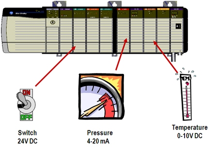
• Input modules interface directly to devices such as switches and temperature sensors.
• Input modules convert many different types of electrical signals such as 120VAC, 24VDC, or 4-20mA, to signals which the controller can understand.
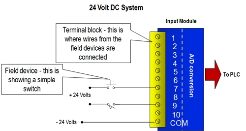
• Input modules convert real world voltage and currents to signals the PLC can understand. Since there are different types of input devices, there is a wide variety of input modules available, including both digital and analog modules.
Discrete vs. Analog Modules :
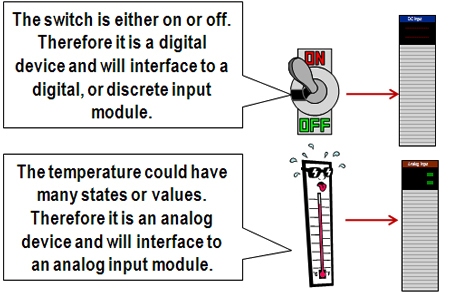
• Discrete Modules use only a single bit to represent the state of the device. For example, a switch is either open or closed. Therefore, the bit is either a 0 (switch is open) or a 1 (switch is closed). Discrete modules are also known as Digital modules.
• Analog Modules use words to represent the state of a device. An analog signal represents a value… For example, the temperature could be 5, 9, 20, 100, etc degrees. Analog modules use a value, such as 52, rather than a 0 or 1 to represent the state of the device.
Discrete Modules :
• Devices that are either on or off , such as a pushbutton , get wired to discrete modules. Discrete modules come in a variety of types, such as 24VDC or 120VAC. You can buy discrete modules that allow you to typically connect anywhere from 2 to 32 devices, with the most popular being 16 devices.
• Since it takes only 1 bit to represent the state of a device, a 16 point discrete module only requires 16 bits of memory in the controller to store the states of all the points on the module.
Analog Modules :
• Devices that have a number associated with them, such as a temperature sensor , get wired to analog modules. Analog modules come in a variety of types, such as 4 to 20 mA or 0 to 10 VDC. You can buy analog modules that allow you to connect anywhere from 2 to 16 devices.
• Since it takes 1 word to represent a number, a 16 point analog module requires 16 words of memory in the controller to store the value of all the numbers on the module. Each word in a PLC takes 16 or 32 bits (depending on the PLC), therefore it takes 16 or 32 times the amount of PLC memory to store analog points vs. digital points.
Output Modules :
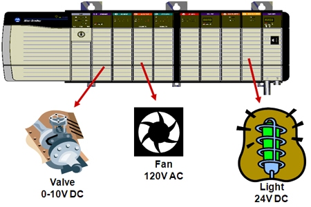
• Output modules interface directly to devices such as motor starters and lights.
• Output modules take digital signals from the PLC and convert them to electrical signals such as 24VDC and 4 mA that field devices can understand.
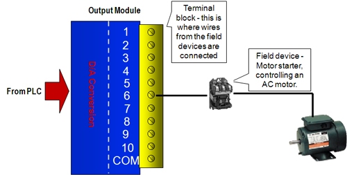
• Output modules take a signal from a PLC and convert it to a signal that a field device needs to operate. Since there are different types of output devices, there is a wide variety of output cards available, including both digital and analog cards.
Basic Components of a PLC System :
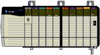
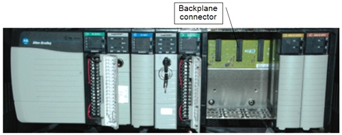
Chassis/Backplane :
All PLCs need some method of communicating between the controller, I/O and communications modules. Here are three ways used to accomplish this communications between the various components that make up the PLC system.
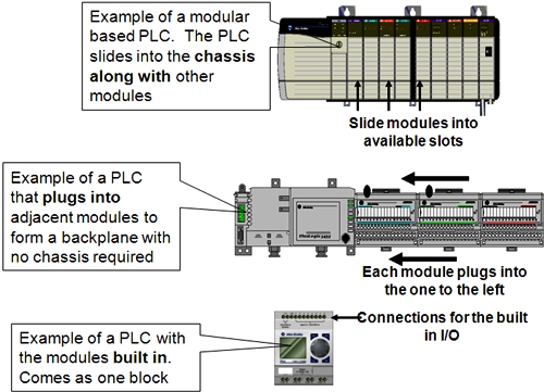
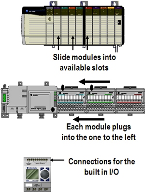
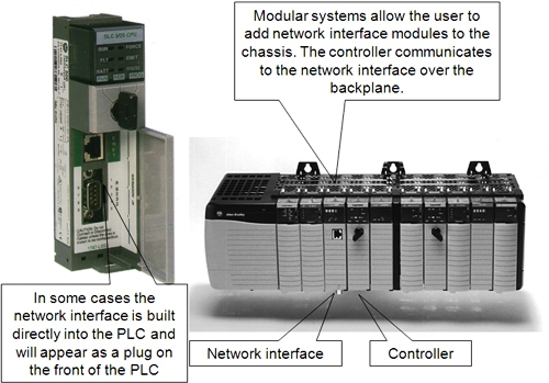
• Modules are installed in the same chassis as the PLC and communicate over the chassis backplane.
• Modules are designed to “plug” into each other. The interconnecting plugs form a backplane there is no chassis.
• Modules are built into the PLC and modules come together in one physical block. The backplane in this case is transparent to the user.
Below is an example of a backplane in a chassis based system. You can see the backplane in the area where the modules are not inserted. The modules have connectors that plug into the black connectors on the backplane. All of the connectors on the backplane are connected together electrically.
Chassis and Backplane Examples :
Benefits of the Different Forms :
• Great flexibility in choice of modules. Modules can be easily installed or removed without affecting other modules.
• Great flexibility in choice of modules. In some cases modules cannot be removed without “breaking the chain” and affecting all modules downstream no chassis cost.
• Low cost solution but limited flexibility, generally used in smaller, simpler systems.
Basic Components of a PLC System :
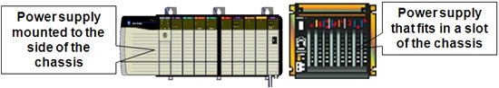
Power Supply :
A power supply is needed to provide power to the PLC and any other modules. Power supplies come in various forms :
• Power supply modules that fit into one of the slots in a chassis.
• External power supplies that mount to the outside of a chassis.
• Stand alone power supplies that connect to the PLC or I/O through a power cable.
• Embedded power supplies that come as part of the PLC block.
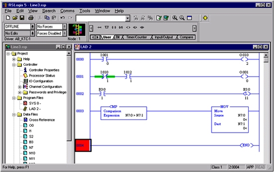
Programming Software :
Software that runs on a PC is required to configure and program PLCs.
• Different products may require different programming software.
,br> • Software allows programs to be written in several different languages
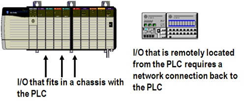
Network Interface :
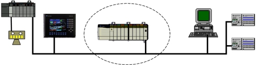
Most PLCs have the ability to communicate with other devices. These devices include computers running programming software, or collecting data about the manufacturing process, a terminal that lets an operator enter commands into the PLC, or I/O that is located in a remote location from the PLC. The PLC will communicate to the other devices through a network interface.
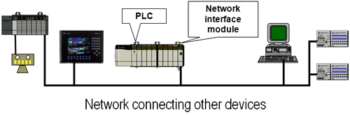
Network Interface :
PLC Control Panel :
• Typically, PLCs are installed in enclosures, on a “panel”.
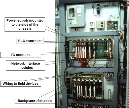
PLCs are part of a Control System :
The PLC system is the center of a control system, but it is not the entire control system. There are several other key pieces that must be added to a PLC system to make a complete control system. Examples are :
• Operator terminals.
• Networks.
• Distributed I/O devices (I/O that is in a different location then the PLC).