PLC to Control Valve Input and Output Signals Loop
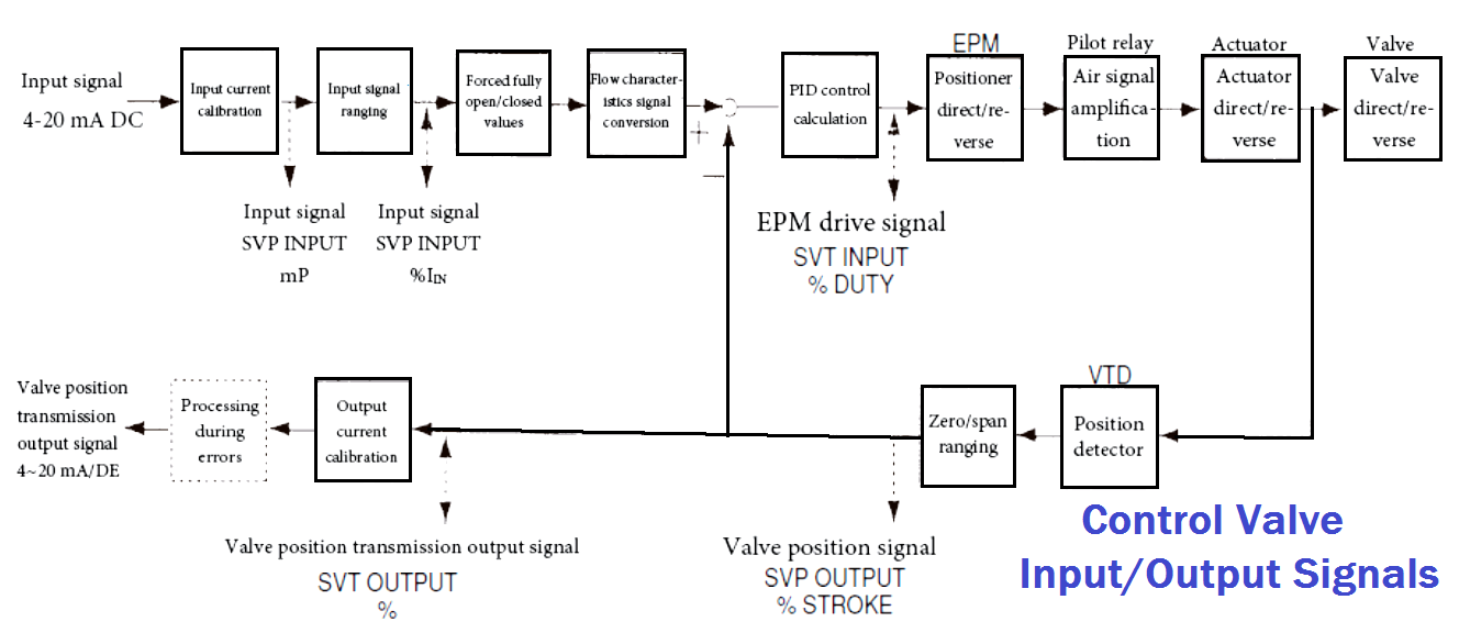
In the above block diagram, the 4-20mA input signal coming from PLC Analog Output module and going to control valve positioner.
Valve positioner converts the 4-20mA input signal into equivalent pressure signal (say for example 3 to 15 psi range) and feeds this equivalent pressure signal to the actuator then actuator position the valve stem accordingly.
The control valve stem travel feedback 4-20mA output going to PLC Analog Input module and eventually displays the valve opening/closing position in the graphics page for the operator.