How-to do Remote Seal Level Transmitter Calibration Procedure. Level Transmitter LRV and URV calculations and configurations for level measurement.
Remote Seal Level Transmitter Calibration Procedure
Factory-filled hydraulic pressure seal assemblies are adjusted for the values specified by the customer. During the adjustment procedure the pressure seals and transmitters are at equal height.
The calibration temperature is 20°C. When defining the calibration values you must take into account the difference in height between seal flanges and transmitter, because the hydrostatic pressure of the fill fluid affects the zero adjustment. Zero suppression and elevation can be determined as shown in examples 1 and 2.
The temperatures of capillary tubes, transmitter and pressure seal flanges affect the zero. The coefficients given in the technical specifications can be utilized when defining the calibration values for a specific temperature distribution.
The total effect of seal flange locations and temperature distribution on zero suppression can be determined by summing the partial effects . The signs must be taken into account in the calculations.
Level Measurement in Open Vessel
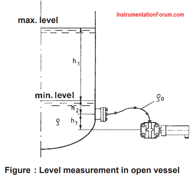
Example 1: Open vessel (Fig.)
Span p1 , is as follows:
P1 = h1 ρ g
= 3.50 m × 980 kg/m3 × 9.81 m/s2 = 33.6 kPa
Zero suppression p2 is as follows:
P2 = (h2ρ+ h3ρO) × g
= (1.00 m × 980 kg/m3 + 0.90 m × 960 kg/m3 × 9.81 m/s2
= 18. 1 kPa
Level Measurement in Closed Vessel
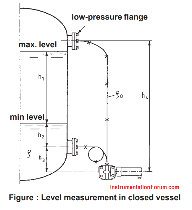
Example 2: Closed vessel (Fig.)
Span p1, is as follows:
P1 = h1 ρ g
= 3.50 m × 980 kg/m3 × 9.81 m/s2 = 33.6 kPa
Zero elevation (suppression) p2 is as follows:
P2 = (h3-h4) ρ0g + h2ρg =
(0.90-6.00)m × 960 kg/m3 × 9.81 m/s2 + 1.00 m × 980 kg/m3 × 9.81 m/s2
P2 = -38.4 kPa (negative result = elevated-zero range)
h1= difference in height between maximum and minimum level (3.50 m)
h2 = height of minimum level from (+) - flange (1.00 m)
h3 = difference in height between (+)- flange and transmitter(0.90m)
h4 = difference in height between (-)-flange and transmitter(6.00 m)
ρ = density of measured fluid (980 kg/m3)
ρ0 = density of fill fluid (960 kg/m3)
g = acceleration of gravity (9.81 m/s2)
NOTE: If transmitter is higher than the (+)-flange, the difference h3 will have a negative value.