Resistance thermometer Working Principle
What is an RTD?
RTD stands for Resistance Temperature Detector. RTDs are sometimes referred to generally as resistance thermometers. The American Society for Testing and Materials (ASTM) has defined the term resistance thermometer as follows:
Resistance thermometer, n. - a temperature-measuring device composed of a resistance thermometer element, internal connecting wires, a protective shell with or without means for mounting a connection head, or connecting wire or other fittings, or both. [Vol. 14.03, E 344 - 02 § 3.1 (2007).]
An RTD is a temperature sensor which measures temperature using the principle that the resistance of a metal changes with temperature. In practice, an electrical current is transmitted through a piece of metal (the RTD element or resistor) located in proximity to the area where temperature is to be measured.
The resistance value of the RTD element is then measured by an instrument. This resistance value is then correlated to temperature based upon the known resistance characteristics of the RTD element.
How do RTDs Work?
RTDs work on a basic correlation between metals and temperature. As the temperature of a metal increases, the metal’s resistance to the flow of electricity increases.
Similarly, as the temperature of the RTD resistance element increases, the electrical resistance, measured in ohms (Ω), increases. RTD elements are commonly specified according to their resistance in ohms at zero degrees Celsius (0° C).
The most common RTD specification is 100 Ω, which means that at 0° C the RTD element should demonstrate 100 Ω of resistance.
Platinum is the most commonly used metal for RTD elements due to a number of factors, including its
(1) chemical inertness,
(2) nearly linear temperature versus resistance relationship,
(3) temperature coefficient of resistance that is large enough to give readily measurable resistance changes with temperature and
(4) stability (in that its temperature resistance does not drastically change with time).
Other metals that are less frequently used as the resistor elements in an RTD include nickel, copper and Balco.
RTD elements are typically in one of three configurations:
(1) a platinum or metal glass slurry film deposited or screened onto a small flat ceramic substrate known as “thin film” RTD elements, and
(2) platinum or metal wire wound on a glass or ceramic bobbin and sealed with a coating of molten glass known as “wire wound” RTD elements.
(3) A partially supported wound element which is a small coil of wire inserted into a hole in a ceramic insulator and attached along one side of that hole. Of the three RTD elements, the thin film is most rugged and has become increasingly more accurate over time.
Why are RTDs sometimes called 2, 3 or 4 wire RTDs? And why would I want one RTD wire configuration instead of another?
A simple rule of thumb is that the more wires an RTD has the more accurate it is. The entire RTD assembly is not platinum. Among other issues, constructing an RTD in that manner would for most purposes be prohibitively expensive.
As a result, only the small RTD element itself is made of platinum. As a practical matter the resistance value of the RTD element would be useless without a means to communicate that resistance to an instrument. Accordingly, insulated copper wires typically connect the RTD element to the measuring instrument.
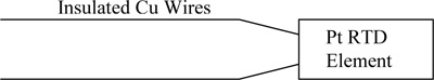
Like platinum, copper has a resistance value. Resistance along the copper lead wires can impact the resistance measurement determined by the instrument connected to the RTD.
Two wire RTDs do not have a practical means for accounting for the resistance associated with the copper lead wires which reduces the extent to which the resistance measured can be accurately correlated to the temperature of the RTD element.
As a result, two wire RTDs are least commonly specified and are generally used where only an approximate value for temperature is needed.
Three wire RTDs are the most common specification for industrial applications. Three wire RTDs normally use a Wheatstone bridge measurement circuit to compensate for the lead wire resistance as shown below.
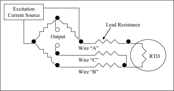
In a 3 wire RTD configuration, Wires “A” & “B” should be close to the same length. These lengths are significant because the intention of the Wheatstone bridge is to make the impedances of wires A and B, each acting as an opposite leg of the bridge, cancel the other out, leaving Wire “C” to act as a sense lead carrying a very small (microamperage range) current.
4 Wire RTDs are even more accurate than their 3 wire RTD counterparts because they are able to completely compensate for the resistance of the wires without having to pay particular attention to the length of each of the wires. This can provide significantly increased accuracy at the relatively low cost of increased copper extension wire.
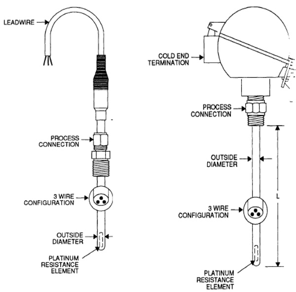
What are the common components of an RTD?
1. RTD platinum resistance element: This is the actual temperature sensing portion of the RTD. Elements range in length from 1/8" to 3". There are many options. The standard temperature coefficient is an alpha of .00385 and the standard resistance is 100 Ω at 0° C.
2. RTD Outside diameter: The most common outside diameter is ¼" in the US or 6mm (.236") for non-US applications. However, outside diameters range from .063" to .500"
RTD Tubing Material: 316 Stainless steel is commonly used for assemblies up to 500° F. Above 500° F it is advisable to use Inconel 600.
3. RTD Process Connection: Process connection fittings include all standard fittings used with thermocouples (i.e. compression, welded, spring-loaded, etc.).
4. RTD Wire Configuration: RTDs are available in 2, 3 and 4 wire configuration. 3 wire configurations are the most common for industrial applications. Teflon and fiberglass are the standard wire insulation materials. Teflon is moisture resistant and can be used up to 400° F. Fiberglass can be used up to 1000° F.
5. RTD cold end termination: RTDs can terminate on the cold end with plugs, bare wires, terminal heads and any of the reference junctions common to thermocouples.