The necessary steps for designing an SIS from conception through decommissioning are described in the safety life cycle.
Before the safety life cycle model is implemented, the following requirements should be met:
• Complete a hazard and operability study
• Determine the SIS requirement
• Determine the target SIL
Safety Life Cycle Model
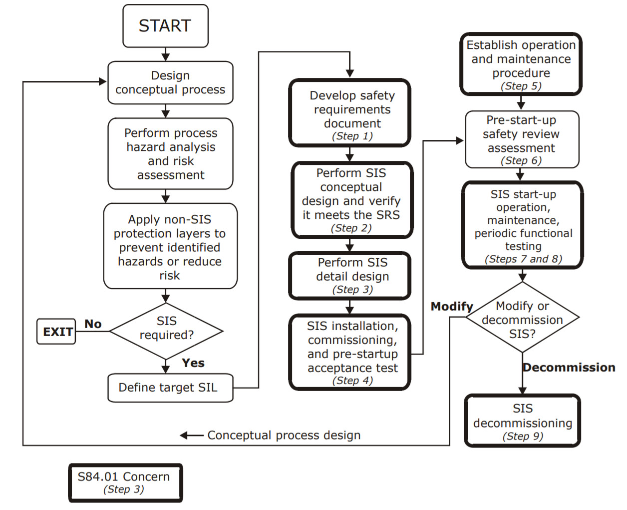
Developing an SIS Using the Safety Life Cycle
1 Develop a safety requirement specification (SRS).
An SRS consists of safety functional requirements and safety integrity requirements. An SRS
can be a collection of documents or information.
Safety functional requirements specify the logic and actions to be performed by an SIS
and the process conditions under which actions are initiated. These requirements
include such items as consideration for manual shutdown, loss of energy source, etc.
Safety integrity requirements specify a SIL and the performance required for executing
SIS functions. Safety integrity requirements include:
• Required SIL for each safety function
• Requirements for diagnostics
• Requirements for maintenance and testing
• Reliability requirements if the spurious trips are hazardous
2 Develop the conceptual design, making sure to:
• Define the SIS architecture to ensure the SIL is met (for example, voting 1oo1, 1oo2, 2oo2, 2oo3).
• Define the logic solver to meet the highest SIL (if different SIL levels are required in a single logic solver).
• Select a functional test interval to achieve the SIL.
• Verify the conceptual design against the SRS.
3 Develop a detailed SIS design including:
• General requirements
• SIS logic solver
• Field devices
• Interfaces
• Energy sources
• System environment
• Application logic requirements
• Maintenance or testing requirements
Some key ANSI/ISA S84.01 requirements are:
• The logic solver shall be separated from the basic process control system (BPCS).
• Sensors for the SIS shall be separated from the sensors for the BPCS.
• The logic system vendor shall provide MTBF data and the covert failure listing, including the frequency of occurrence of identified covert failures.
Note Triconex controllers do not contain undiagnosed dangerous faults that are statistically
significant.
• Each individual field device shall have its own dedicated wiring to the system I/O. Using a field bus is not allowed!
• The operator interface may not be allowed to change the SIS application software.
• Maintenance overrides shall not be used as a part of application software or operating procedures.
• When online testing is required, test facilities shall be an integral part of the SIS design.
4 Develop a pre-start-up acceptance test procedure that provides a fully functional test of the SIS to verify conformance with the SRS.
5 Before startup, establish operational and maintenance procedures to ensure that the SIS functions comply with the SRS throughout the SIS operational life, including:
• Training
• Documentation
• Operating procedures
• Maintenance program
• Testing and preventive maintenance
• Functional testing
• Documentation of functional testing
6 Before start-up, complete a safety review.
7 Define procedures for the following:
• Start-up
• Operations
• Maintenance, including administrative controls and written procedures that ensure safety if a process is hazardous while an SIS function is being bypassed
• Training that complies with national regulations (such as OSHA 29 CFR 1910.119)
• Functional testing to detect covert faults that prevent the SIS from operating according to the SRS
• SIS testing, including sensors, logic solver, and final elements (such as shutdown valves, motors, etc.)
8 Follow management of change (MOC) procedures to ensure that no unauthorized changes are made to an application, as mandated by OSHA 29 CFR 1910.119.
9 Decommission an SIS before its permanent retirement from active service, to ensure proper review.
Reference: Triconex