Analog input and output values of the expansion modules EM 231, EM 232 and EM 235, as well as of CPU 224XP are displayed digitally in the INTEGER data word format. It is necessary to make conversions to ensure correct interpretation and processing. These conversions are explained using the download attached. The download contains both the “Scale” library with conversion functions and the sample program “Tip038” for better understanding.
1. Scaling
The following diagrams show how the input and output values are scaled.
The terms “unipolar”, “bipolar” and “20% offset” are explained here. These are important for, among others, the STEP 7 Micro/Win - Instruction Wizard PID (Tools > Instruction Wizard > PID Controller).
Unipolar scaling is done only in the positive or negative value range (Fig. 01 shows an example for an analog input value of between 0 and 32000).
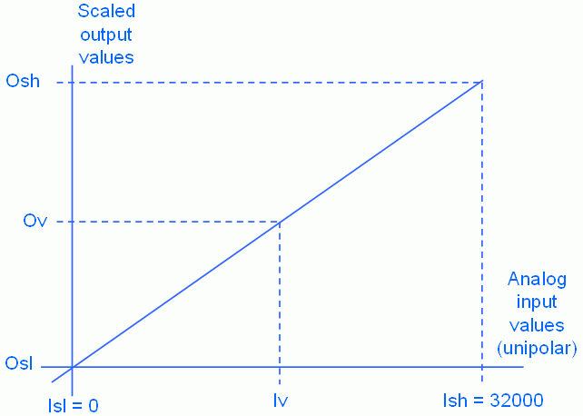
Fig. 01
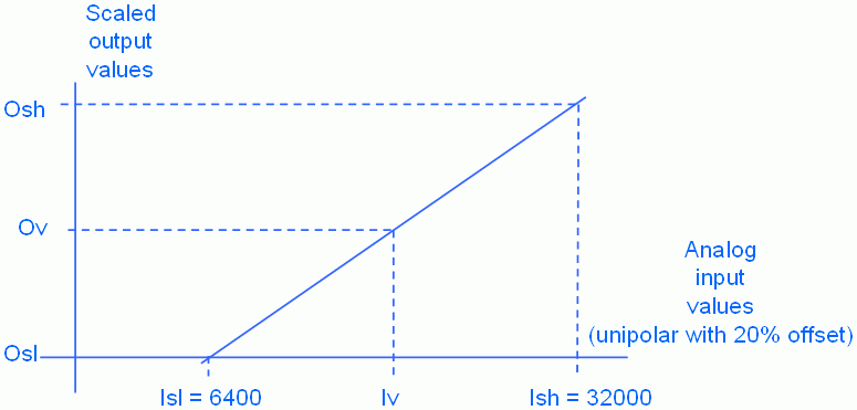
In the case of unipolar scaling with a 20% offset, the lower limit of the value range is 20% of the upper limit (Fig. 02 shows an example for an analog input value of between 6400 and 32000).
Fig. 02
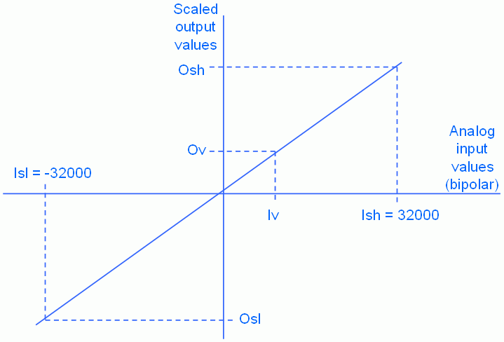
Bipolar scaling is done in the positive and negative value range (Fig. 03 shows an example for an analog input value of between -32000 and 32000).
Fig. 03
The following table explains the abbreviations used:
| Parameter | Description |
|---|---|
| Ov | Scaled output value (Output value) |
| Iv | Analog input value (Input value) |
| Osh | Upper scale limit for the scaled output value (Output scale high) |
| Osl | Lower scale limit for the scaled output value (Output scale low) |
| Ish | Upper scale limit for the scaled input value (Input scale high) |
| Isl | Lower scale limit for the scaled input value (Input scale low) |
Table 01
2. Formula
The following formula is derived from the diagram for calculating the scaled value:
Ov = (Osh - Osl) / (Ish - Isl) * (Iv - Isl) + Osl
3. Library
3.1 Description of the “Scale” library
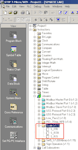
The “scale.mwl” library contains the function blocks for converting the scaling from data type INTEGER to REAL (S_ITR), from REAL to REAL (S_RTR) and from REAL to INTEGER (S_RTI).
Fig. 04
3.2 Scaling the analog input in the output data format REAL (S_ITR)
The S_ITR function permits you to convert the analog input signal into a normalized value between 0.0 and 1.0 (type REAL).
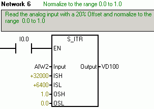
Fig. 05
3.3 Scaling change to the data type format REAL (S_RTR)
The S_RTR function permits you to convert value ranges within the REAL format (e.g., convert the input value between 0.0 and 1.0 to the output range in percent).
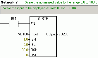
Fig. 06
3.4 Converting to the analog output scaling format INTEGER (S_RTI)
The S_RTI function converts a REAL number to the analog output data type INTEGER.
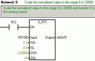
Fig. 07
Reference - Siemens
