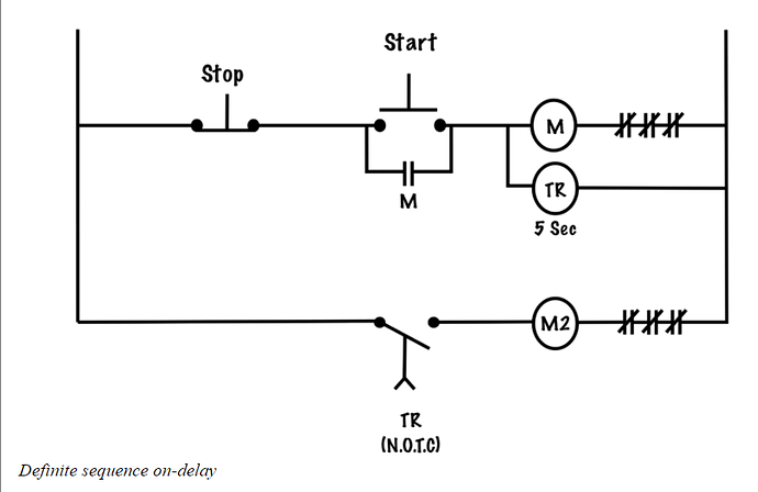
The above circuit shows a standard three-wire circuit for a single motor starter M1. In parallel with M1 is a time-delay relay (TR) whose normally open, timed to close (NOTC) contacts identify it as an on-delay timer. These timed contacts are in series with motor starter M2. The above switching arrangement will allow two motors to be controlled from a single pushbutton station and will guarantee that M2 energizes five seconds after M1 is energized. Once both motor starters are engaged, the motors will continue to run until the stop button is pressed.
If an overload occurs on motor M2, then only that motor will stop, but if motor M1 develops an overload and its OLR contacts open, then the coil will de-energize and its 2-3 holding contact will open, disconnecting the timer coil from the source of supply. Once the on-delay coil is de-energized, its contacts will revert to their original state instantly, so motor M2 will also be de-energized.
If more than two motors are to be sequenced in this fashion, we would simply scale up this switching arrangement by connecting additional timer relays in parallel with each motor starter so that as one motor starts, it also begins a countdown for the next one in sequence.
Reference
Basic Motor Control by Aaron Lee and Chad Flinn is used under a CC BY 4.0 Licence.
