On a combination fuel unit, the gas/oil switch must be set for the proper fuel. The following sequence (’’‘Figure 2’’’) occurs with power present at the program relay (PR) input terminals and with all other operating conditions satisfied.
Pre-Purge Cycle
When the burner switch (BS) is turned “on,” and controls wired in the “limit” and “fuel valve interlock” circuits are closed and no flame signal is present, the “blower motor start circuit” is powered, energizing the blower motor starter (BMS). The load demand light (LDL) turns on. When firing oil, the air compressor motor starter (ACMS) (if provided) is also powered. The air purge valve (APV) (Nos. 5 and 6 oil only) remains de-energized.
At the same time, the program relay signals the modulating damper motor (MDM) to open the air damper. The damper begins to open and drives to its full open or high fire position. Opening the damper motor allows a flow of purging air through the boiler prior to the ignition cycle.
On certain boilers, the circuitry will include a high fire switch (HFS). The purpose of the switch is to prove that the modulating damper motor (MDM) has driven the damper to the open position during the prepurge cycle. In this instance, the “high fire proving circuit” is used.
The controls wired into the “running interlock circuit” must be closed within 10 seconds after the start sequence. In the event any of the controls are not closed at this time, or if they subsequently open, the program relay will go into a safety shutdown.
At the completion of the high fire purge period, the program relay signals the modulating damper motor (MDM) to drive the air damper to its low fire position.
To ensure that the system is in low fire position prior to ignition, the low fire switch (LFS) must be closed to complete the “low fire proving circuit.” The sequence will stop and hold until the modulating damper motor (MDM) has returned to the low fire position and the contacts of the low fire switch (LFS) are closed. Once the low fire switch is closed, the sequence is allowed to continue.
NOTE:
The ignition trial cannot be started if flame or a flame simulating condition is sensed during the pre-purge period. A safety shutdown will occur if flame is sensed at this time.
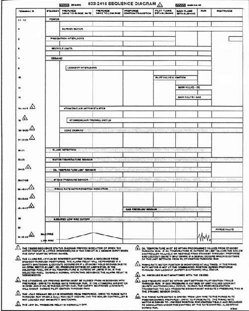
‘’‘Figure 3: 833-2416 Sequence’’’
Ignition Cycle
The ignition transformer (IT) and gas pilot valve (GPV) are energized from the appropriate pilot ignition terminal.
NOTE:
An oil-fired burner may be equipped with an oil pilot tather than a gas pilot. The ignition sequence of both is identical.
The pilot flame must be established and proven by the flame detector (FD) within a 10 second period in order for the ignition cycle to continue. If for any reason this does not happen, the system will shut down and safety lockout will occur.
With a proven pilot, the main fuel valve(s) (OV or MGV) is/are energized and the main fuel valve light (FVL) in the panel is lighted. The main flame is ignited and the trial period for proving the main flame begins. It lasts 10 seconds for light oil and natural gas, and 15 seconds for heavy oil. At the end of the proving period, if the flame detector still detects main flame, the ignition transformer and pilot valve are de-energized and pilot flame is extinguished.
NOTE:
If the main flame does not light, or stay lit, the fuel valve will close. The safety switch will trip to lock out the control. Refer to flame loss sequence (section D) for description of action.
WARNING!
 The cause for loss of flame or any other unusual condition should be investigated and corrected before attempting to re-start. Failure to follow these instructions could result in serious personal injury or death!
Run Cycle
With main flame established, the program relay releases the modulating damper motor (MDM) from its low fire position to control by either the manual flame control (MFC) or the modulating control (MC), depending upon the position of the manual-automatic switch (MAS). This allows operation in ranges above low fire.
With the manual-automatic switch (MAS) set at automatic, subsequent modulated firing will be at the command of the modulating control (MC), which governs the position of the modulating damper motor (MDM). The air damper and fuel valves are actuated by the motor through a linkage and cam assembly to provide modulated firing rates.
Normal operation of the burner should be with the switch in the Manual-Automatic position and under the direction of the modulating control. The Manual position is provided for initial adjustment of the burner over the entire firing range. When a shutdown occurs while operating in the Manual position at other than low fire, the damper will not be in a closed position, thus allowing more air than desired to flow through the boiler. Excess airflow subjects the pressure vessel metal and refractory to undesirable conditions. The effectiveness of nozzle purging is lost on a No. 6 oil burner.
The burner starting cycle is now complete. The (LDL) and (FVL) lights on the panel remain lit. Demand firing continues as required by load conditions.