A programmable logic controller (PLC), also referred to as a programmable controller, is the name given to a type of computer commonly used in commercial and industrial control applications.
PLC
PLCs differ from office computers in the types of tasks that they perform, and the hardware and software they require to perform these tasks. While the specific applications vary widely, all PLCs monitor inputs and other variable values, make decisions based on a stored program, and control outputs to automate a process or machine.
The basic elements of a PLC include input modules or points, a central processing unit (CPU), output modules or points, and a programming device. The type of the input modules or points used by a PLC depends upon the types of the input devices used. Some input modules or points respond to digital inputs, also called discrete inputs, which are either on or off. Other modules or inputs respond to analog signals.
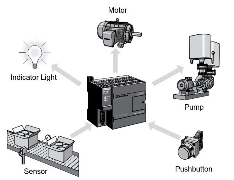
Fig. 1 Devices controlled by PLC
These analog signals represent machine or process conditions as a range of voltage or current values. The primary function of a PLC’s input circuitry is to convert the signals provided by these various switches and sensors into logic signals that can be used by the CPU. The CPU evaluates the statuses of the inputs, outputs, and other variables as it executes a stored program. The CPU then sends signals to update the status of the outputs.
The output modules convert the control signals from the CPU into digital or analog values that can be used to control various output devices. The programming device is used to enter and change the PLC’s program, to monitor and change the stored values. Once entered, the program and associated variables are stored in the CPU. In addition to these basic elements, a PLC system may also incorporate an operator interface device of some sort to simplify monitoring of the machine or process.
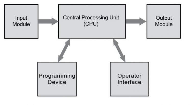
Fig. 2 Basic elements
Hard-Wired Control
Prior to PLCs, many control tasks were performed by contactors, control relays and other electromechanical devices. This is often referred to as hard-wired control.
Circuit diagrams had to be designed, electrical components specified and installed, and wiring lists created. Electricians would then wire the necessary components to perform a specific task. If an error was made, the wires had to be reconnected correctly. A change in function or system expansion required extensive component changes and rewiring. SIMATIC software is the universal configuring and programming environment for SIMATIC controllers, human machine interface systems and process control systems. SIMATIC software with STEP 7 and numerous engineering tools supports all phases of product deployment, from hardware configuration of the system and parameterization of modules to service of the installed system. PLC programming can be done also with the help of Simatic Manager, which provides the possibility to write programs in three programming languages:
Ladder logic (LAD)
It is one programming language used with PLCs. Ladder logic incorporates programming functions that are graphically displayed to resemble the symbols used in hard-wired control diagrams.
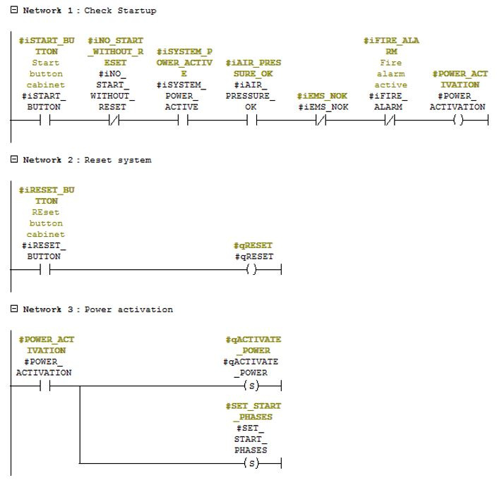
Fig. 3 Example of logical schema in LAD
Statement List (STL)
list of instructions. This editor allows you to create a program by entering the mnemonic commands. In this editor you can create programs that can not be created in the LAD and FBD editor. Programming in STL is very similar to the assembler language, but it’s more specific.

Fig. 4 Example of logical script in STL
Function Block Diagram (FBD)
functional block diagram. This editor displays the program in the form of conventional logic circuits. There are no contacts, but there are equivalent functional units. This editor doesn’t use the term “power flow”, as in the LAD, it expresses a similar concept of the control flow through the FBD logic blocks.
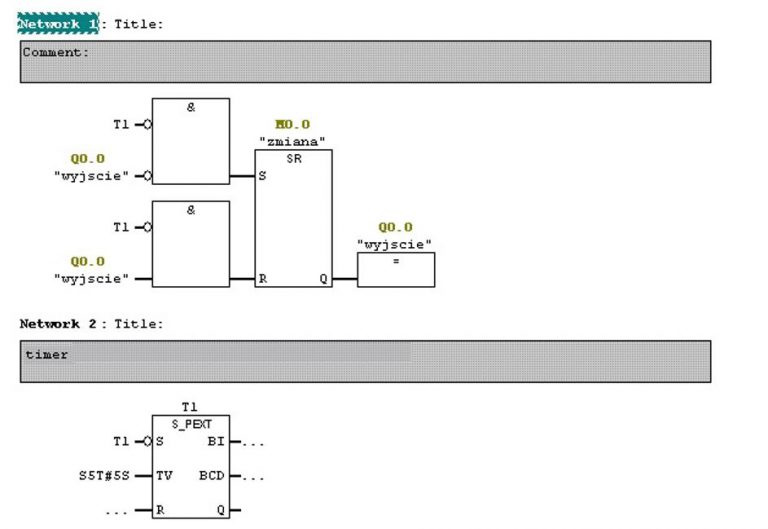
Fig. 5 Example of logical schema in FBD
Motor Starter Example
This example will show the practical aspect of programming in Step 7 with a real, existing part of a system. A motor starter coil (M) is wired in series with a normally open, momentary Start push-button, a normally closed, momentary Stop push-button, and normally closed overload relay (OL) contacts.
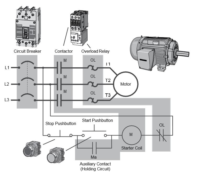
Fig. 6 Electrical schema of the starter
PLC Motor Control
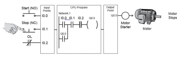
The motor control application can also be accomplished with a PLC. In the following example, a normally open Start push-button is wired to the first input (I0.0), a normally closed Stop push-button is wired to the second input (I0.1), and a normally closed overload relay contacts (part of the motor starter) are connected to the third input (I0.2). These inputs are used to control normally open contacts in a line of ladder logic programmed into the PLC.
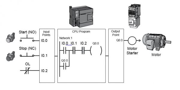
Initially, I0.1 status bit is a logic 1 because the normally closed (NC) Stop push-button is closed. I0.2 status bit is a logic 1 because the normally closed (NC) overload relay (OL) contacts are closed. I0.0 status bit is a logic 0, however, because the normally open Start push-button has not been pressed.
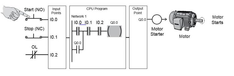
Normally the open output Q0.0 contact is also programmed on Network 1 as a sealing contact. With this simple network, energizing the output coil Q0.0 is required to turn on the motor. When the Start push-button is pressed, the CPU receives a logic 1 from input I0.0. This causes the I0.0 contact to close. All three inputs are now a logic 1. The CPU sends a logic 1 to the Q0.0 output. The motor starter is energized and the motor starts.
The output status bit for Q0.0 is now equal to 1. On the next scan, when the normally open contact Q0.0 is solved, the contact will close, and the output Q0.0 will stay on, even if the Start push-button is released.
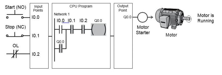
When the Stop push-button is pressed, the input I0.1 turns off, the I0.1 contact opens, the output coil Q0.0 de-energizes and the motor turns off.
Advantages of PLCs
PLCs are not only capable of performing the same tasks as hard-wired control, but are also capable of covering a larger array of complex applications. In addition, the PLC program and electronic communication lines replace much of the interconnecting wires required by hardwired control.
Therefore, hard-wiring, though still required to connect the field devices, is less intensive, that’s why correcting the errors and modifying the application is much easier.
Here are the main advantages of the PLCs:
- Smaller physical size than the hard-wire solutions;
- Easier and faster to make changes;
- PLCs have integrated diagnostics and override functions;
- Diagnostics are centrally available;
- Applications can be immediately documented;
- Applications can be duplicated faster and less expensively.