Check valves are used to protect critical equipment in a pipeline from flow reversal. This is crucial in cases of pumps and compressors where backflow can damage internal parts. These are automatically operated owing to the pressure difference between the upstream and downstream sides of the valve. These open with forward flow and close against the reverse flow, thus no need for actuators or operators. These are also called non-return valves.
An interesting application is where the check valve connects primary and secondary systems of the pipeline, and they avoid the backflow in case of a pressure surge in the secondary systems.
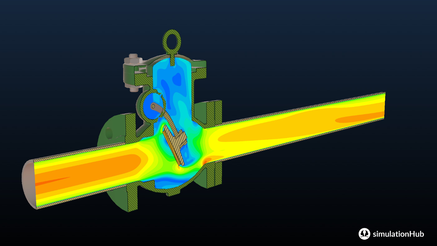
A type of check valve is: Swing check valve

Figure 1: Swing Check Valve
Understanding the Swing Check Valve
The valve closure member consists of a valve disc that is connected to a hinge/shaft with a lever. Another arrangement is the lever and an external spring which is used in high-pressure flow applications. In this the valve closure member swings about a hinge or shaft which is outside the seat. The forward flow pushes the disc away from the seat while the reverse flow causes the disc closure. As compared to other types of check valves swing check valves give the lowest pressure drop.
To elaborate :
Valve closure element: Disc
Valve closure mechanism:
a) Lever connected to a hinge
b) A lever connected with an external spring
Its advantages are :
a) Low-Pressure drop
b) Easy to maintain
Its disadvantage is that it cannot be used in the pulsating type of flows.
About the simulations
The simulation was performed with the objective of obtaining the flow performance coefficients of the DN100 swing check valve. The angle of the opening varies from 10 degrees to 45 degrees of opening. The class of the valve is 150. As shown below is the image of the flow lines of the swing check valve at maximum opening. The maximum gross Cv is 547 with a corresponding coefficient of hydrodynamic torque -1.2196 and pressure drop 0.69 bar. Below let’s have a look at some visualization of the results.
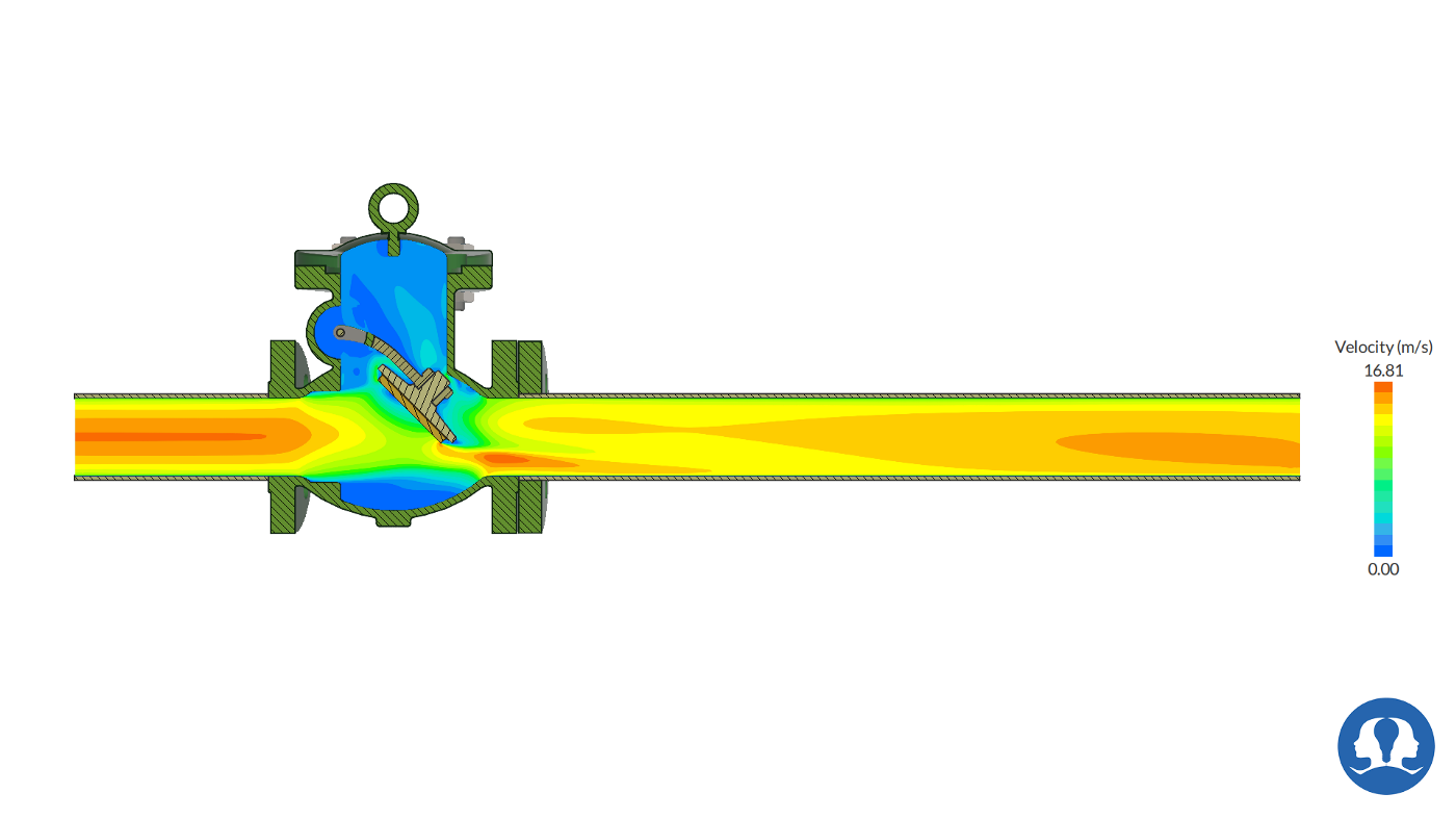
Figure 2: Velocity contour for the particular opening of the Swing Check Valve
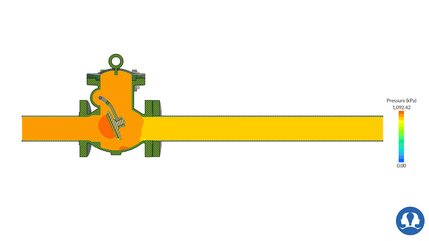
Figure 3: Pressure contour for the particular opening of the Swing Check Valve
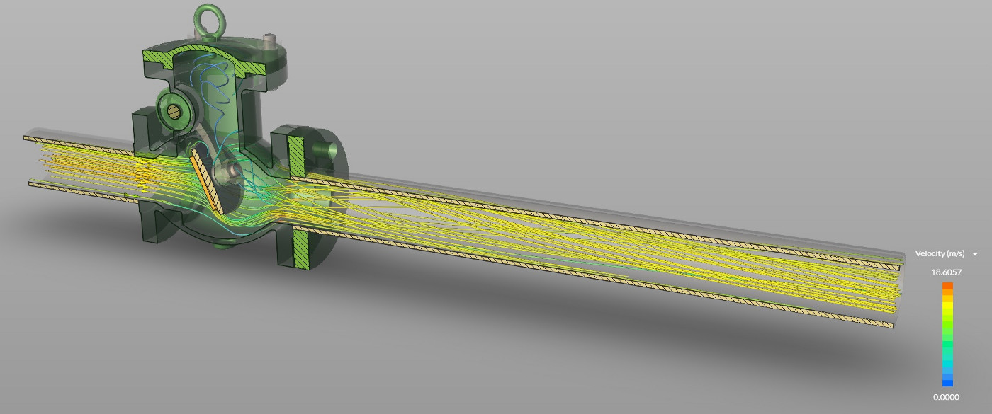
Figure 4: Streamlines for the particular opening of the Swing Check Valve.
The animation reveals the variation in the velocity of the flow with a change in opening conditions.
To know more about the simulation visit: Simulation of Swing Check Valve using Autonomous Valve CFD