In electrical systems, we use the terms “single-phase” and “three-phase” fairly often, so a brief description of them will help us moving forward.
Single-phase systems are the simplest electrical circuits. They require only two lines: one for power to go in and the other is a return path for current. These are often called Line 1 and Line 2, or Line 1 and Neutral. Current only has one path to travel in a single-phase circuit, and all of the control circuits that we will be looking at are single-phase.
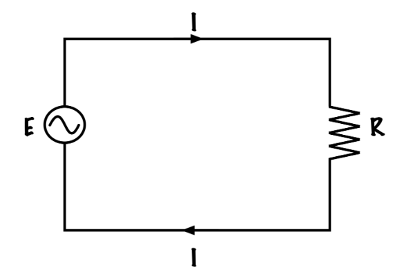
AC single phase circuit
Three-phase systems are bit more complex. They use three current carrying conductors, called Line 1, Line 2, and Line 3, which have a 120° phase shift in the voltage and current waveforms between them. Each of these conductors are connected to a three-phase load, like a three-phase motor.
When in operation, a balanced three-phase load (such as a motor) has each of its three line’s current values cancel each other out, and so it does not require a return conductor. These loads can be connected in Wye or Delta configuration, which will be covered later in this text.
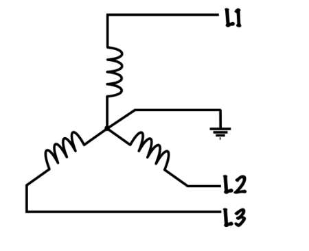
3-phase circuit
Unbalanced three-phase loads are mainly connected in the Wye configuration where the central point is used as a neutral to carry any stray return currents. In practice a motor is always a balanced three-phase load.
All of the power circuits that we will be looking at will be three-phase.
All of the control circuits that we will be looking at will be single-phase.
Reference
Basic Motor Control by Aaron Lee and Chad Flinn is used under a CC BY 4.0 Licence.