One of the key design parameters in safety instrumented system (SIS) design is the architecture or voting arrangements of the various subsystems that comprise a safety instrumented function (SIF).
The architecture, or voting arrangement, is essentially the use of redundant pieces of equipment for the purpose of creating the ability to tolerate a failure of one component and still have the SIF perform its action.
Selection of an appropriate voting arrangement will consider the failure modes of the SIS equipment, the level of safety that must be achieved and the rate of spurious failures and the associated consequences (financial or otherwise) of a spurious trip.
In process industry SIS design there are several common voting arrangements. For the purposes of this discussion I will focus on the sensor subsystem, but the same discussion will also apply to the logic solver and final element subsystems.
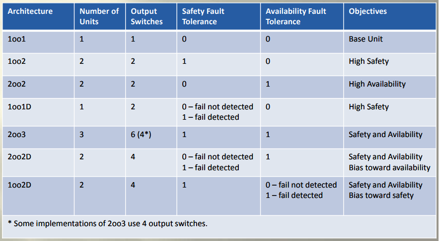
The most common voting arrangements used in industry are as follows:
- One-out-of-one (1oo1) – a.k.a., simplex
- One-out-of-two (1oo2)
- Two-out-of-two (2oo2)
- Two-out-of-three (2oo3)
There are two parts to the voting arrangement description. The first number is the number of devices that must “vote” to cause a trip for the trip to occur. The second number is the total number of devices. Thus, in a 2oo2 voting arrangement, 2 devices must vote to trip, out of a total of two device for the shutdown action to be taken.
SIS Voting System
Before discussing the value of the different voting arrangements in different situations, it’s important to first understand the failure modes of SIS equipment.
SIS equipment can fail in one of two ways
- Safe (Spurious, Initiating, Overt)
- Dangerous (Inhibiting, Covert)
When an SIS suffers a safe failure, the SIS will cause the SIF to activate and shutdown the plant when there was no actual demand or need to shut the plant down.
These failures are often referred to as spurious failures or nuisance failures since production was unnecessarily stopped. The are also called initiating failures because the initiate the action of the SIF when it was not required, and overt failures because the failure is overt- meaning it announces its presence by causing a shutdown of the plant.
As an example, a safe failure of a shutoff valve could include breakage of the instrument air connection, which then causes the actuator to depressure and the valve to fail to its closed position.
In this case a shutdown occurred unnecessarily when there was no hazard present. Dangerous failures are the opposite. Dangerous failures are also called inhibiting failures because they inhibit the SIF from taking action when it is called to do so, and covert failures because the failure does not reveal itself, laying in wait until the SIF is called on to take its safety action but it cannot.
As an example, a dangerous failure of a valve could include the ball of a ball valve getting jammed against the seat preventing it from turning.
The failure itself does not cause anything to happen and will not evidence itself until the SIS calls on the valve to close, but since the valve is jammed it will not close and thus inhibits or prevents the SIF from taking the required safety action.
Knowing these two failure modes is critical because the use of redundancy can only affect one of these modes depending on the voting arrangement.
Now that failure modes of been described, let’s go through each of the voting arrangements and describe them physically and compare their probability of failing dangerously as well as their spurious trips.