Split Range Control Loop
In a split range control loop, output of the controller is split and sent to two or more control valves. The splitter defines how each valve is sequenced as the controller output changes from 0 to 100%.
In most split range applications, the controller adjusts the opening of one of the valves when its output is in the range of 0 to 50% and the other valve when its output is in the range of 50% to 100%.
Unlike the cascade and selective control scheme the split range control has one measured and more then one manipulated variable. Since there is only one controlled output , we have only one controlled signal which is thus spilt in to several parts each affecting one of the final control element which are available in the system .
In other words we can say that we have one output from controller and split in to no of signal depends upon how many final control elements are there. So finally we control the process by one output and many final control element.
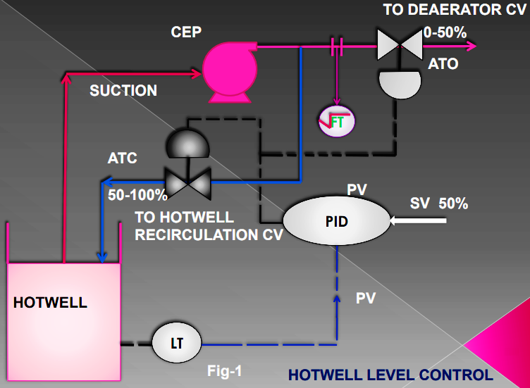
An “Split range control ” control strategy involves a controller and many final control elements depends upon the various process. In fig-1 we are going to control the hotwell level control for steam turbine . we consist some equipments and some instruments for control the process. We have a motive to control the hotwell level at 50% desired level .
When level goes down below 50% then controller generate the command on the basis of error and open the recirculation valve to maintain the level at 50%.Now when the level goes greater then 50% then the same command open the deaerator FCV to dump the excess water to deaerator to control the level .
So in this process we are controlling two CV with single output in such a manner that when level are increasing then deaerator CV will open and When level gose down then Hotwell recirculation CV will open and control the desired level.Deaerator CV will work from 0 to 50% and Hotwell recirculation will work from 50 to 100%.So finaly split control are using in the given process to control the hotwell level accurately
SYMBOLS
FT, Flow transmitters.
PV, Process variables.
SV, Set variables.
LIC, Level controller.
LT, Level transmitter.
CV, Control valves.
Author - Ashvani Shukla