Start,shutdown procedure for Boiler
1 Like
Boiler Preparation, Start-Up and Shutdown
A boiler must be carefully and properly prepared for start-up. This is a step by step process, and all plants will have their own procedure based on the role that the steam system plays in that plant. It is important to note that the boiler, and steam system, are often prepared and started before the process units in a large plant, because many of the other processes depend on the steam system for startup or ongoing power supply. If something has been overlooked in the boiler preparation it may mean costly downtime later on.
Boiler preparation procedures will also vary depending on the reason that the boiler has been shut down. Obviously, more steps would have to be taken to prepare a newly constructed and commissioned boiler than one which has been shut down overnight to replace a leaking fitting. In this module we will look at some general considerations that apply to either new boilers, or those that have undergone extensive maintenance work. As a point of reference, we will assume that all safety systems and devices on the boiler, such as low level switches, and safety relief valves, were verified as operational during the commissioning period, that the boiler and external piping and fittings have been checked for leaks, and that the boiler has a valid inspection certificate (if not, the Chief Engineer will need to contact the local Boiler Inspector and make appropriate arrangements).
START-UP PREPARATION
Several checks must be made before a boiler can be started. These checks include the boiler itself, the feedwater system, and the fuel and draft systems. As well, old boilers must be dried out and new boilers, boiled out.
Boiler
Before closing up and filling the boiler, it must be inspected both internally and externally. The internal inspection is to make certain that it is free from scale, oil, tools, debris and other foreign material. In particular, if furnace refractory work has been done it is important to make sure that all debris is removed, so that after start-up any material on the floor can be assumed to be the result of fallen refractory that requires replacement.
All internal baffles should be checked to see that they are secure, particularly if they are steam drum internals. If maintenance has been done on the water side of a watertube boiler all tools which were taken into the boiler should be checked off as removed, to ensure that nothing has fallen into a water tube. Check that the burners are clean and ready for firing. Check soot blower alignment and clearance of movement.
Following these steps the boiler can be closed up. New handhole and manhole gaskets should be used and should be coated with a graphite paste to prevent them from sticking to the metal. This will make them easier to remove when the boiler is next shut down. Before filling the boiler, check that the blow-off valves are closed and a vent valve open, so that air may escape from the boiler as it is filling.
Feedwater System
Verify the proper operation of the feedwater system if it has been out of service along with the boiler. Ensure that it is open all the way back to the primary source of water, that the feedwater treatment equipment is functioning, the raw and treated water tanks are at their proper levels, the deaerator is operational and full, and that the pumps are in service.
Fuel and Draft Systems
Verify that all necessary valves in the main and pilot fuel supply systems are open, and that the oil is at the correct temperature and pressure, or that the gas is at the correct pressure. Ensure that the main gas cock and other related valves are in their proper positions to initiate the start-up ignition sequence.
Start the draft fan and check for normal operation. Stroke the air dampers to make sure they are free to move their full range. Make sure that there is an adequate supply of air available for the furnace; if it uses inside air check the room openings and the space around the damper inlet vanes, if it uses external air check that the intake screens are clear. This point is especially important in the winter when frost may close them off.
Boiler Dry-Out
If new refractory has been installed in the furnace it will have to be slowly dried out before raising the furnace to normal operating conditions. New refractory contains water which will flash into steam and damage the material if it does not have a chance to evaporate before reaching normal furnace operating temperature. This is done by creating a very light fire in the furnace, sufficient to speed up the evaporation but not to harm the refractory.
Before starting the fire, fill the boiler to the normal level with treated, deaerated water. Leave a vent open to prevent pressure build up during the dry out period. Maintain the water level to replace any that leaves the drum due to the heating process. Next, ensure that the furnace has been adequately purged. Then, according to manufacturer’s recommendations, start a light fire and maintain it from 48 hours to several days, depending on the amount of refractory replaced.
Boiling Out
If the boiler is new it will have to be “ boiled out”. The boil-out removes all the grease, welding debris, dirt, and oil from construction. If this is not done the boiler will experience major water level control problems when started up, as the greases and oils contribute to foaming conditions. In addition, important sensing lines for instruments and gage glasses can get plugged up. In extreme cases the accumulation of debris in one area of the boiler could impede water circulation enough to cause overheating and tube failure.
The boiler is cleaned by heating the water, adding detergent type chemicals, and then periodically blowing down to dislodge dirt and remove sludge. On large units the process may be repeated several times over a period of days. The chemicals used are usually soda ash and caustic soda, as well as trisodium phosphate and sodium silicate. The amounts of each chemical to use varies with the overall cleaning program.
START-UP
There are three major areas of attention when starting up a boiler: obtaining stable ignition, bringing the boiler up to normal operating conditions, and preparing and pressurizing the steam headers.
Ignition
Although boilers have many different specific ignition systems, they all follow the same basic sequence of steps:
- Pre-purge of the furnace.
- Reduction of air flow for stable ignition.
- Pilot burner ignition
- Main burner ignition.
Small boilers often have completely automatic ignition systems. Some older, or specialized boilers, may have completely manual systems. Most boilers have a combined system, where some steps, such as 1 and 2 above, are done automatically, and the remaining steps require the operator to perform specific tasks within a set time period. As an example of a typical ignition procedure we will look at this type of system in the following discussion.
Fig. 1 shows the essential equipment components of an ignition system. Not all boilers will have equipment identical to this, but it is fairly typical of most systems apart from minor differences. To keep things simple we have chosen to describe a gas fired boiler. Pilot gas is supplied to the pilot burner through a pressure control valve and solenoid valve. Gas for the main burner is supplied through a pressure control valve, a flow control valve, the electrically operated automatic shut-off valves, and finally the main gas cock. The automatic shut-off valves are arranged in a “double block and bleed” system that ensures no gas can enter the furnace when the boiler is shut down. When shut down, valves A and B are both closed and vent C is open. When the boiler is operating, A and B are both open and C is closed. These valves are designed so that A and B will close and C will open, all automatically, in the event of a boiler shutdown. During start-up, C will close automatically, but A and B need to be manually actuated (latched) to open.
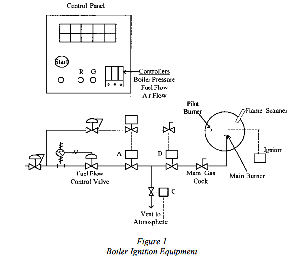
Fig. 1 also shows an outline of the local control panel for the boiler. This displays the alarms, fan switch, ignition switch, ignition status indicators (red and green lights), and the steam pressure, fuel flow, air flow and water level controls. To avoid clutter, all the normal indicators and recorders are not shown.
Before the ignition sequence can begin, all the boiler shutdown switches must be in their “permissive” states. For example, the water level must be within acceptable limits, and the fuel pressure must be within its acceptable limits. We will assume that all the required operating conditions have been satisfied.
We will also assume that all valves are in their proper start-up positions. In particular, the gas cock on the main gas line must be closed, and there is usually a position switch to check that this is the case. If this valve is not closed the ignition sequence will not be permitted to proceed. If the boiler has a superheater, it is common to open the superheater vent at this time, so that it does not overheat due to lack of steam flow.
Before starting the fan, the operator must place the steam pressure (also known as the Boiler Master), fuel flow and air flow controllers in manual mode, and set their outputs to the required ignition positions. The ignition sequence is then initiated by closing the fan switch. The programmer will automatically put the boiler into a pre-purge mode, with the required amount of air flow, for a specified time period. The minimum air flow setting on the air flow controller will be temporarily overridden during the purge period. Following the purge, a light on the panel will indicate “Purge Complete”, and the air flow dampers will return to the position assigned by the air flow controller.
The operator can now push the pilot igniter push button. This button must be held until the flame scanner senses a stable pilot burner flame. Initially, a red light goes on to indicate that the igniter is in operation, and that pilot gas is flowing to the burner. When pilot ignition occurs, the adjacent green light will go on. The operator may now release the igniter push button, since a stable pilot flame has been sensed.
The operator must now act efficiently to complete the ignition procedure, since the programmer will only allow for a specific time period to obtain main burner ignition. The next step is to open valves A and B by manually resetting them, usually this means repositioning a latching lever. Vent valve C will close automatically. Finally the operator must manually open the main gas cock next to the boiler. Gas will now flow to the main burner, and it will ignite from the pilot flame. If these steps are done in time, the ignition sequence is complete, and the firing rate can be increased to bring the boiler up to operating conditions.
Boiler Warm-Up
The rate at which a boiler can be brought up to normal operating status depends on its size, and the length of time it has been shut down. In general, the larger and colder a boiler is, the longer we should take to pressurize it. Care must be taken not to thermally shock the metal and refractory, and to allow thermal expansion to occur.
Following ignition, the firing rate is increased on manual control. Care must be taken to ensure that the fuel and air flow rates are within safe ratio limits. Most boiler control systems will, in fact, have built-in “cross-limiting” combustion controls to make certain that the air flow and fuel flow rates are properly matched. The water level control system can usually be placed on automatic as soon as the boiler is started.
While the boiler is being slowly pressurized the operator can make a visual check of its condition. Look for red “hot spots” on the metal surface. These would indicate that refractory has fallen away. Check the furnace draft pressures, and compare them to earlier log sheets, to make sure that combustion gases are passing normally through the furnace and convection passages. Check the fan and feedwater pumps for normal operation. Now is a good time to verify the proper operation of the low water level alarm, and to blow the water column clear of sediment.
As boiler pressure approaches its normal setpoint, the steam pressure and combustion control system can be switched over to automatic. From previous log sheets and recording charts verify that the boiler is performing “as expected”. Enter in the daily log a summary of the start-up events.
Steam Header Warm-Up
Steam headers conduct steam from the boiler to other equipment in the plant. They must be properly warmed up to avoid thermal stress, and to remove condensate as it forms. If this is not done, severe water hammer will result during the overall plant start-up. In some cases sufficient piping damage has occurred to cause loss of life. To see how the process of warming up and drying out steam headers is accomplished, we need to first take a quick look at how they are arranged in a plant.
Header arrangements are different depending on whether only one, or more than one, boiler produces into the header. Fig. 2 shows the two basic arrangements.
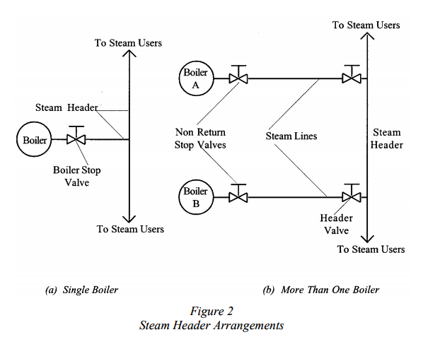
In Fig. 2(a) a single boiler produces steam into the header. The block valve at the outlet of the boiler is called the boiler stop valve, and is usually of the standard gate valve design. The piping downstream of the valve is referred to as the steam header (or steam main), and it supplies all the plant equipment taking steam at that pressure. In Fig 2(b) two boilers, A and B, are producing into the same steam header. Each boiler is equipped with a non-return type valve (described in the module “Introduction to Valves”), and a header valve. The section of line between the two valves is referred to as the boiler steam line, to distinguish it from the steam header.
In addition to these arrangements, plants can have several different steam headers, identified by the pressures at which they operate. Thus, for example, a plant may have a 10,000 kPa steam header, a 2000 kPa steam header, and a 350 kPa steam header. Alternatively, these may be referred to as the high, intermediate, and low pressure steam headers. Each of these headers may have its own boilers and steam users. It is common that these headers are connected in sequence; that is, the high pressure header “lets down” to the intermediate pressure header, which, in turn, lets down to the low pressure header.
With these arrangements in mind, let’s return to the discussion of how to warm up and dry out the piping during start-up. In a single boiler plant the easiest way to do this is to open up the boiler stop valve and header drains as soon as ignition has been obtained. As the boiler begins to produce steam, and slowly pressurizes, the header will be warmed from the steam. Condensate, which forms as the steam meets the cold piping, will be removed quickly from the header by the drains. By the time the boiler is up to its normal operating pressure the headers should be warm and dry. Alternatively, it is possible to leave the header isolated until the boiler reaches its operating pressure. At this point the stop valve is slowly opened and the header warmed up. As before, it is very important that the header drain valves are opened during this procedure.
In a plant with more than one boiler the procedure is somewhat different. There are two possible situations that require different procedures:
-
All the boilers have been shut down. The boiler we are starting up is the first to go on line . All steam headers are cold.
-
There are other boilers in the plant which are already on line. The main steam headers are already warmed up and pressurized.
The first case is treated exactly like the warm up procedure for a single boiler plant. The headers are opened up following ignition and warm up as the boiler is pressurized. In the second case the main steam headers are already in service but we still need to warm up the boiler steam line. Even though this is a relatively short length of piping compared to the overall steam header system, nevertheless, it is extremely hazardous to put this line into full service without warming it up and drying it out.
The procedure for opening up a boiler into a pressurized steam header is referred to as “cutting” the boiler into the header, and is described in Section VII of the ASME code. Fig.3 shows the related equipment.
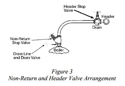
To start the warm up, open the drain on the non-return valve. It is important to know that this drain is actually connected internally to the downstream side of the valve plug. Next, open the header valve a slight amount, allowing steam to flow from the steam header into the boiler steam line and out the drain. The boiler steam line will thus be warmed up with steam flowing back from the steam header. Any condensate present will be forced out the drain valve. The header valve can be slowly opened wide when the pressure has equalized between the steam header and the boiler steam line.
During this time the boiler has been slowly pressurizing. When boiler pressure is still a few kPa below the header pressure, the non-return valve spindle is backed off (that is, turned in the open direction) to about the one quarter open position. Note that, due to the check valve nature of this valve, it doesn’t actually open at this time, it will only begin to open when the boiler pressure exceeds the header pressure. By backing off the valve handle we are simply giving the valve some room to open when the pressure is high enough. As boiler pressure continues to rise, and finally exceeds header pressure, the non-return valve will begin to open until it reaches the one quarter limit that we set it at. We can now slowly open the valve the remainder of its travel, and close the drain. The boiler is now fully on line.
SHUTTING DOWN A BOILER
When a boiler has to be removed from service for maintenance, inspection, or layup, the following procedure should be followed:
-
Before shutting the boiler down, give it a good blowdown to remove as much sediment as possible. Stop when the drain runs clear.
-
Put the boiler steam pressure control in manual mode, and slowly reduce the firing rate. Watch the main steam header pressure to make sure that the other boilers are taking up the load. Do not reduce the firing rate below that necessary to maintain a stable flame.
-
When the boiler is at the minimum firing rate the fuel can be shut off at the main gas cock. Alternatively, this is often a good time to test the low water level shutdown switch, or some other boiler interlock. If this method is chosen make sure you note it in the logbook.
-
Allow the fan to post-purge the furnace with a reduced air flow, and then shut the fan down. Be particularly careful not to let the fan supply large amounts of cold air into the furnace in the winter.
-
Close the boiler header stop valve.
-
Open a steam drum vent valve when the boiler pressure drops to slightly above atmospheric pressure. This will prevent a vacuum from forming (not doing this has resulted in a fatality in recent years, when maintenance personnel proceeded to open the manhole cover from the water drum of a boiler which had drawn a vacuum).
If the boiler is going to be shut down for an extended period of time it will need a proper lay-up. This topic is described in the module “Boiler Maintenance”.
2 Likes
CHECKS TO BE MADE ON THE BOILER BEFORE STARTING THE AUXILIARIES
- All manhole doors on the boiler and ducts are to be closed.
- All dampers in the flue gas path, primary air path, & secondary air path shall be checked for their correct position.
- Power supplies for all electrically operated dampers shall be switched on.
- Breakers of all auxiliaries shall be kept in service position.
- D C control supplies shall be ensured for all auxiliaries.
- Local push buttons shall be kept released.
- All breakers shall be selected for remote operation.
- Valves status shall be checked on the boiler.
- Check up the drum level and keep it at (-) level.
- Main steam valve at boiler outlet and its bypass valve shall be kept closed.
- Drain valves before main steam stop valve and before ESV shall be kept opened.
- All super heater vents and drains shall be kept opened.
- All sampling valves shall be kept opened.
- Chemical dosing tank levels both for phosphate and hydrazine shall be checked and if necessary shall be topped up.
- Condenser hot well level and deaerator levels shall be checked and levels shall be made up if necessary.
- Boiler seal trough shall be filled with water and seal trough overflow shall be maintained.
- Before boiler light up the TG set shall be kept on barring gear and the CW system shall be kept in service.
- Auxiliary cooling water pumps shall be kept in service.
- One boiler feed pump shall be kept in service.
- Fuel oil pump shall be kept in service.
- Fuel oil heating system shall be kept in service and the fuel oil shall be kept under circulation to raise its temperature.
1 Like