A completed wiring diagram can help with the physical installation of wires. To aid in the development of a wiring diagram, it is useful to start with the circuit’s schematic diagram and the numbering system.
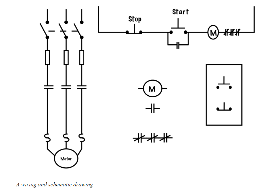
Consider the figure above. It includes a three-wire schematic diagram as well as the equivalent control components and the power circuit. In this example, there is no control transformer, so we will be taking control power directly from the line. The control circuit power is taken from the load side of the overcurrent devices and the line side of the power contacts.
Once the schematic diagram has been properly numbered, each device will have two numbers identifying it, one wire on the line side, and one on the load side. For example, in a three-wire circuit, the stop button gets wires 1 and 2, while the start button and the holding contact each get wire numbers 2 and 3 (hence the term “2-3 contact“).
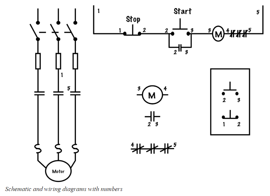
Once all the devices have been properly numbered, we simply play connect the dots. Each point that shares the same number is electrically common and needs to be connected together. Use straight lines and only connect wires at terminal points on equipment.
Make sure that all connections happen at termination points or “terminal to terminal.” In practice, we usually only connect a maximum of two wires to any one point and never make a “free-air splice.”
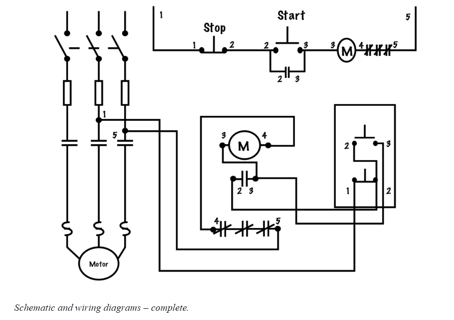
The figure above illustrates each of the strengths that wiring and schematic diagrams have: Schematic diagrams are easy to read and used to logically troubleshoot a circuit, while wiring diagrams show how equipment is physically connected together.
Reference
Basic Motor Control by Aaron Lee and Chad Flinn is used under a CC BY 4.0 Licence.