Objectives:
- To find the coefficient of discharge of a venturi meter
- To find the coefficient of discharge of an orifice meter
Theory:
Venturi meter
The venturi meter has a converging conical inlet, a cylindrical throat and a diverging
recovery cone (Fig.1). It has no projections into the fluid, no sharp corners and no sudden
changes in contour.
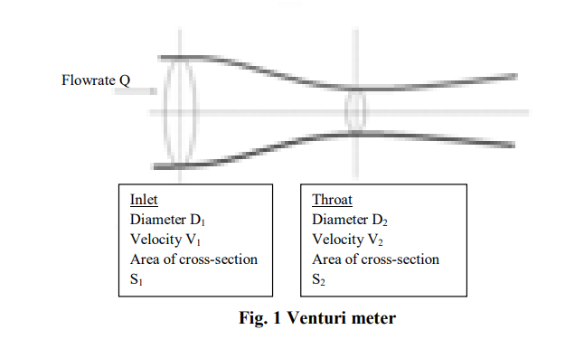
The converging inlet section decreases the area of the fluid stream, causing the velocity to increase and the pressure to decrease. At the centre of the cylindrical throat, the pressure will be at its lowest value, where neither the pressure nor the velocity will be changing.
As the fluid enters the diverging section, the pressure is largely recovered lowering the velocity of the fluid. The major disadvantages of this type of flow detection are the high initial costs for installation and difficulty in installation and inspection.
The Venturi effect is the reduction in fluid pressure that results when a fluid flows through a constricted section of pipe. The fluid velocity must increase through the constriction to satisfy the equation of continuity, while its pressure must decrease due to conservation of energy: the gain in kinetic energy is balanced by a drop in pressure or a pressure gradient force.
An equation for the drop in pressure due to Venturi effect may be derived from a combination of Bernoulli’s principle and the equation of continuity.
The equation for venturi meter is obtained by applying Bernoulli equation and equation of continuity assuming an incompressible flow of fluids through manometer tubes. If V1 and V2 are the average upstream and downstream velocities and ρ is the density of the fluid, then using Bernoulli’s equation we get,
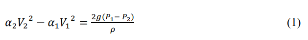
where α1and α2 are kinetic energy correction factors at two pressure tap positions.
Assuming the density of fluid to be constant, the equation of continuity can be written as:
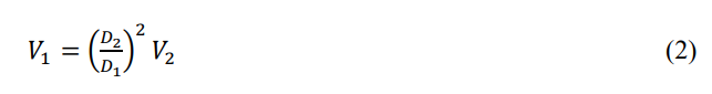
where D1 and D2 are the diameters of the pipe and the throat respectively.
Eliminating V1 from equation (1) and equation (2) we get,
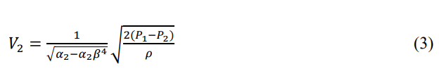
where β is the ratio of the diameter of throat to that of diameter of pipe.
If we assume a small friction loss between the two pressure taps, the above equation (3) can
be corrected by introducing an empirical factor Cv (Coefficient of discharge) and written as:
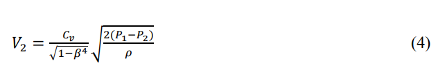
The small effect of the kinetic energy factors α1 and α2 is also taken into account in the
definition of Cv.
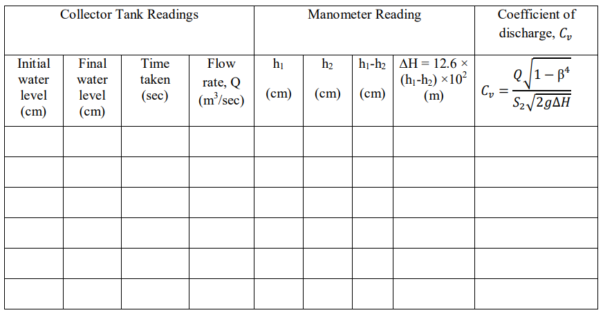
Volumetric flow rate Q can be calculated as:
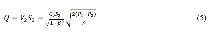
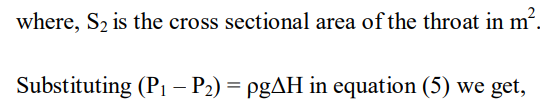
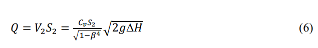
where ΔH is the manometric height difference × (specific gravity of manometric fluid –
specific gravity of water).
Orifice meter
An orifice meter is essentially a cylindrical tube that contains a plate with a thin hole in the middle of it. The thin hole essentially forces the fluid to flow faster through the hole in order to maintain flow rate.
The point of maximum convergence (vena contracta) usually occurs slightly downstream from the actual physical orifice.
This is the reason why orifice meters are less accurate than venturi meters, as we cannot use the exact location and diameter of the point of maximum convergence in calculations.
Beyond the vena contracta point, the fluid expands again and velocity decreases as pressure increases.
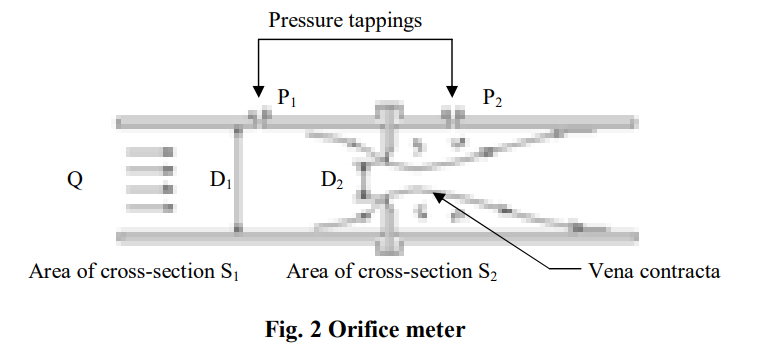
Figure 2 shows an orifice meter with the variable position of vena contracta with respect to the orifice plate.
By employing the continuity equation and Bernoulli’s principle, the volumetric flow rate through the orifice meter can be calculated as described previously for venturi meter.
Hence,
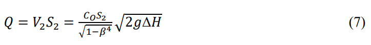
where Co is the orifice discharge coefficient, S2 is the area of cross-section of the orifice, V2 is the flow velocity through the orifice, β is the ratio of the diameter of orifice to that of the diameter of pipe, ΔH is the manometric height difference × (specific gravity of manometric fluid – specific gravity of water), and g is the acceleration due to gravity.
Read Also:
- Integral Flow Orifice Assembly
- What is an Orifice Flange?
- Types of Orifice Tappings
- What are the different Orifice Plates?
- Turndown ratio of Orifice Plates
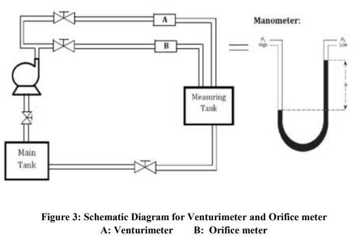
Figure 3 depicts the schematic layout of the test setup consisting of the venturi meter and the orifice meter.
Procedure:
-
Check all the clamps for tightness.
-
Check whether the water level in the main tank is sufficient for the suction pipe of pump to
be completely immersed. -
For measurement through venturi, open the outlet valve of the venturi meter line and close
the valve of the orifice meter line. -
For a good amount of variation in discharge, close the by-pass valve of pump also.
-
Now switch on the pump.
-
Open the gate valve and start the flow.
-
Remove any bubbles present in the U-tube manometer through air cock valve. Operate the
air cock valve slowly and cautiously to avoid mercury run-away through water. -
Wait till the flow attains a steady state.
-
Close the gate valve of the measuring tank and note the initial water level in the tank.
Measure the time taken for the water level in the tank to reach a certain level and then
calculate the flow rate. Also note the manometer difference. Before taking any
measurements, make sure the flow is stable. -
Repeat the procedure by changing the discharge by slowly opening the by-pass valve and
take the six readings. -
Repeat the same procedure for orifice meter
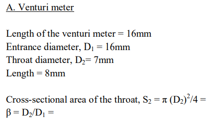
Observations and calculations:
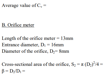

Average value of Co =
Further reading:
- McCabe, W.L., Smith, J.C., and Harriott, P., 1993, Unit Operations of Chemical
- Engineering, McGraw-Hill Inc., Singapore, Chap. 8.
- White, F.M., 2016, Fluid Mechanics, McGraw-Hill Education, New York, Chap. 6.