Measurements should be made to produce the data needed to draw meaningful conclusions from the system under test. These data can be used to minimize or eliminate the vibration and thus the resultant noise. There are also examples where the noise is not the controlling parameter, but rather the quality of the product produced by the system.

For example, in process control equipment, excessive vibration can damage the product, limit pro-cessing speeds, or even cause catastrophic machine failure.
The basic measurement system used for diagnostic analyses of vibrations consists of the three system components shown in Figure

(i) Transducers
In general, the transducers employed in vibration analyses convert mechanical energy into electrical energy; that is, they produce an electrical signal which is a function of mechanical vibration. In the following section, both velocity pickups and accelerometers mounted or attached to the vibrating surface will be studied.
(a) Velocity Pickups
The electrical output signal of a velocity pickup is proportional to the velocity of the vibrating mechanism. Since the velocity of a vibrating mechanism is cyclic in nature, the sensitivity of the pickup is expressed in peak milli-volts/cm/s and thus is a measure of the voltage produced at the point of maximum velocity. The devices have very low natural frequencies and are designed to measure vibration frequencies that are greater than the natural frequency of the pickup.
Velocity pickups can be mounted in a number of ways; for example, they can be stud-mounted or held magnetically to the vibrating surface. However, the mounting technique can vastly affect the pickup’s performance.
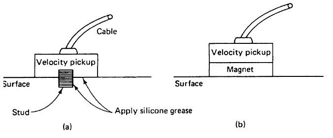
For example, the stud-mounting technique shown in Figure (a), in which the pickup is mounted flush with the surface and silicone grease is applied to the contact surfaces, is a good reliable method. The magnetically mounted pick-up, as shown in Figure (b), on the other hand, in general has a smaller usable frequency range than the stud-mounted pickup. In addition, it is important to note that the magnetic mount, which has both mass and spring like properties, is located between the velocity pickup and the vibrating surface and thus will affect the measurements. This mounting technique is viable, but caution must be employed when it is used.
The velocity pickup is a useful transducer because it is sensitive and yet rugged enough to withstand extreme industrial environments. In addition, velocity is perhaps the most frequently employed measure of vibration severity. However, the device is relatively large and bulky, is adversely affected by magnetic fields generated by large ac machines or ac current carrying cables, and has somewhat limited amplitude and frequency characteristic.
(b) Accelerometers
The accelerometer generates an output signal that is proportional to the acceleration of the vibrating mechanism. This device is, perhaps, preferred over the velocity pickup, for a number of reasons.
For example, accelerometers have good sensitivity characteristics and a wide useful frequency range; they are small in size and light in weight and thus are capable of measuring the vibration at a specific point without, in general, loading the vibrating structure.
In addition, the devices can be used easily with electronic integrating networks to obtain a voltage proportional to velocity or displacement. However, the accelerometer mounting, the interconnection cable, and the instrumentation connections are critical factors in measurements employing an accelerometer. The general comments made earlier concerning the mounting of a velocity pickup also apply to accelerometers.
Some additional suggestions for eliminating measurement errors when employing accelerometers for vibration measurements are shown in Below Figure.
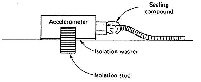
Note that the accelerometer mounting employs an isolation stud and an isolation washer. This is done so that the measurement system can be grounded at only one point, preferably at the analyzer. An additional ground at the accelerometer will provide a closed (ground) loop which may induce a noise signal that affects the accelerometer output. The sealing compound applied at the cable entry into the accelerometer protects the system from errors caused by moisture.
The cable itself should be glued or strapped to the vibrating mechanism immediately upon leaving the accelerometer, and the other end of the cable, which is connected to the preamplifier, should leave the mechanism under test at a point of minimum vibration. This procedure will eliminate or at least minimize cable noise caused by dynamic bending, compression, or tension in the cable.
(ii) Preamplifiers
The second element in the vibration measurement system is the preamplifier. This device, which may consist of one or more stages, serves two very useful purposes: it amplifies the vibration pickup signal, which is in general very weak, and it acts as an impedance transformer or isolation device between the vibration pickup and the processing and display equipment.
Recall that the manufacturer provides both charge and voltage sensitivities for accelerometers. Likewise, the preamplifier may be designed as a voltage amplifier in which the output voltage is proportional to the input voltage, or a charge amplifier in which the output voltage is proportional to the input charge. The difference between these two types of preamplifiers is important for a number of reasons.
For example, changes in cable length (i.e., cable capacitance) between the accelerometer and preamplifier are negligible when a charge amplifier is employed. When a voltage amplifier is used however, the system is very sensitive to changes in cable capacitance. In addition, because the input resistance of a voltage amplifier cannot in general be neglected, the very low frequency response of the system may be affected. Voltage amplifiers, on the other hand, are often less expensive and more reliable because they contain fewer components and thus are easier to construct.
(iii) Processing and display equipment
The instruments used for the processing and display of vibration data are, with minor modifications, the same as those described earlier for noise analyses. The processing equipment is typically some type of spectrum analyzer. The analyzer may range from a very simple device which yields, for example, the rms value of the vibration displacement, to one that yields an essentially instantaneous analysis of the entire vibration frequency spectrum.
More Topics -