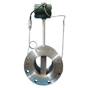
In the process line, flowing fluid strikes the bluff body and vortices are shed alternately on each side of the bluff body. The flow velocity determines the frequency at which the vortices are shed. The shedding of the vortices induces a resonance in the bluff body that is detected by the sensor. From the sensor, pulses are sent to the transmitter where the appropriate loop output is developed…
Input and Output Measurement Standards
Calibration of a vortex shedding flowmeter’s transmitter requires an input standard that can simulate the electrical pulses counted by the transmitter. A frequency generator provides this input.
For a more detailed explanation of a specific frequency generator’s features, see the manufacturer’s literature.
A milliammeter will display the output signal.
Settings and Connections
Before making the connections, determine the vortex shedding frequency. The vortex shedding frequency is usually provided by the manufacturer, but if it is not listed in the manufacturer’s literature, calculate the frequencies using this formula:
Vortex Shedding Frequency = RF x CF x ( URV/TIME)
where:
The vortex shedding frequency is represented in pulses per second or PPS.
PPS = represents the alternate shedding of vortices on either side of the bluff body
RF = stands for reference factor which can be found on the transmitter’s data plate and is usually represented in pulses per US gallon
CF = is the conversion factor, and is a number found in the manufacturer’s conversion table, the CF converts the RF to actual volume or mass flow rate units
URV = is the upper range value in US gallons per minute
TIME = is related to the increment in which the flow is measured
Are span jumpers required to calibrate this transmitter? Refer to the manufacturer’s instructions for the appropriate setting for the coarse span jumpers.
Once the PPS has been determined and span jumpers set in their proper positions, the frequency generator can be connected to the input terminals of the transmitter. The output side of the calibration loop is connected in series. After all the connections are made, set the fine span.
Adjustments and Accuracy
To set the fine span, the frequency generator is set to the upper range value of the transmitter. Adjust the fine span screw until 100% output is indicated on the milliammeter. Once the fine span adjustment has been completed, as indicated by a 20 mA reading on the output standard, adjust the zero.
Disconnect the frequency generator and connect the signal lead to the shield of the coaxial cable.
Zero is adjusted at the low range value so the generator must be set to the appropriate setting following the fine span adjustment.
The zero is adjusted until the output signal matches the input signal at the lowest input value.
The span and zero should be adjusted and readjusted until both are correct.
Perform Five-Point check to verify the instrument’s range accuracy…