High integrity pressure protection system (HIPPS) is a type of safety instrumented system (SIS) designed to prevent over-pressurization of a plant, such as a chemical plant or oil refinery.
The HIPPS will shut off the source of the high pressure before the design pressure of the system is exceeded, thus preventing loss of containment through rupture (explosion) of a line or vessel.
Therefore, a HIPPS is considered as a barrier between a high-pressure and a low-pressure section of an installation.
HIPPS
The main purpose of High Integrity Safety Pressure Protection System (HIPPS) is to execute shutdown action when over pressure happens.
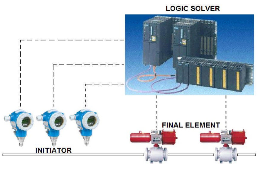
There are three (3) primary components that support the mechanism of HIPPS:
- Initiator,
- Logic Solver, and
- Final Element.
Components
INITIATOR
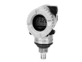
Initiator consists of three (3) SMART electronic pressure transmitters with two wire circuit 4-20mA HART protocol and wired to logic solver.

The function of initiator is simply to detect high pressure condition. In addition, initiator is able to execute self-diagnostic and to send output to certain failure state.
LOGIC SOLVER
Logic Solver retrieves and processes output signal from initiator and executes the result to final element.
Logic solver uses 2oo3 voting logic and de-energizes solenoid valve in the final element when at least two (2) initiators send high pressure signal.

Basically, Logic solver is a Programmable Logic Controller (PLC) with SIL 3 certified and fail-safe redundant I/O for safety related applications.
FINAL ELEMENT
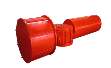
Final Element is a set of component which includes two (2) actuators and two (2) valves (trunnion-mounted double block and bleed ball) that uses 1oo2 voting logic.
The actuator consists of Digital Valve Controller (DVC) and Local Control Panel (LCP).
The main purpose of DVC is to execute partial stroke test which ramps valve gradually during service and operation.
Partial Stroke Test (PST) can be automatically scheduled and initiated by DVC or manually performed by using Local Control Panel (LCP).

In the initial step, the valve will be moved to a predefined value and then to the original location. The default value for the movement of valve is configured to any value up to 30%
Local Control Panel (LCP) has built-in function called Partial Stroke Auto Test Interval which is used to setup the device to run partial stroke test automatically on certain period. LCP has push button which sends commands to the DVC to open, close, or test Safety Shutdown valves.
As indicators, there are three lights in LCP: Green for normal operating position, Red for tripped or fail-safe state, Amber for ready-to-reset status.
Ref: Norr Sytems Korea
