Instrument Loop Diagrams represents detailed drawing showing a connection from one point to control system.
Instrument Loop Diagrams
It could be connection between:
-
Field instrument to control system (or vice versa)
-
Signal from Control Panel to control system (or vice versa)
-
Signal from MCC to control system (or vice versa)
-
Signal form one control system to another system
Classification of Loop diagram
Simple classification can be done as
PCS/DCS loop diagram for controlling and indication
ESD loop diagram for emergency shutting down of instruments
F& G loop diagram for fire and gas related alarms/operations
This can be further classified into subcategories as AI/AO/DI/DO loops
N.B. all signals (voltage or current) is considered with respect to control room. Thus if a signal is going out of control room for closing opening control valve and on/off valve it is considered as an output signal, examples are analog and digital outputs AO/DO and if signals come into control room giving the indication, position, level, temperature, pressure etc it is considered as input signals examples are AI and DI signals.
Analog signals have many values which changes with respect to time like 4 to 20mA for measuring pressure temperature level etc, while digital signal will have only binary values like 0 (off) and 1(on) conditions of on/off valve, status of on/off valve, closed open condition of switches, motor on/off condition etc.
Let us consider the 3 loops individually
PCS/DCS loop
This can be further classified as
PCS AI (Process Control System- Analog Input)
PCS DI (Process Control System -Digital Input)
PCS AO (Process Control System- Analog Output)
PCS DO(Process Control System- Digital Output)
ESD loop
This can be further classified as
ESD DO( Emergency Shutdown Device- Digital Output)
ESD DI ( Emergency Shutdown Device- Digital Input)
ESD AI ( Emergency Shutdown Device- Analog Input)
ESD AO (generally not used because in case of emergency we need immediate action which can be achieved through ESD DO signal)
F&G Loop
FGS DO (Fire and Gas System- Digital Output)
FGS DI (Fire and Gas System-Digital Input)
FGS AI (Fire and Gas System -Analog Input)
FGS AO (generally not used because in case of emergency we need immediate action which can be achieved through FGS DO signal)
Loop diagram shows instrument (in a symbol) and its terminal numbers which are to be connected, instrument cable number, junction box number, terminal number assigned for the specified instrument, multi-pair cable and pair number , marshalling cabinet number, terminal number in marshalling cabinet, control system details (rack, slot, I/O channel). It also clearly indicates location of each equipment by means of border line as a limit.
Loop Diagram usually shows a single control loop which means it could only contains just one input (sensor to control system), just one output (control system to final element) or combination of both
Reference drawing
To have the loop diagram completed and to provide complete information, the following are list of data required along with its source/reference:
-
Instrument Terminal number. Most instrument could be assumed to use (+) and (-). Terminals. Instrument which needs special arrangement such as smoke detector or instrument which in series loop requires manufacturer connection detail to make the cable is properly connected.
-
Junction box terminal number, this information could be obtained from JB wiring connection
-
Marshaling terminal number, this information could be obtained from marshalling wiring connection.
-
I/O point detail information. Obtain this information from I/O assignment which is produced by system integrator or control system vendor.
The purpose of instrument loop diagram
It is used in checking of a correct installation and connection when tested during pre-commissioning, commissioning and also for trouble shooting during operations
A typical loop diagrams is as shown below
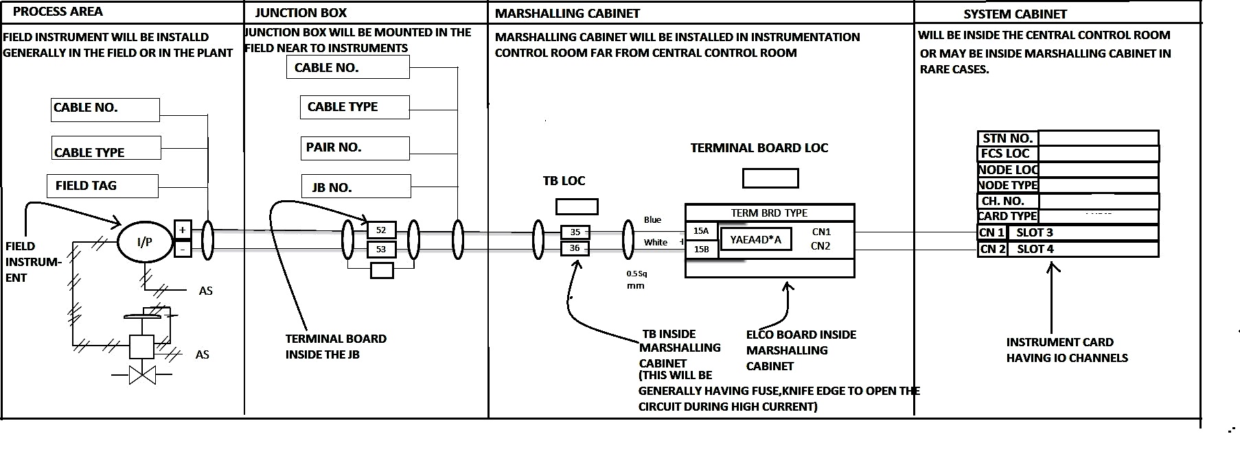
Let me explain every loop and its characteristics one by one……………
A) PCS/DCS LOOP
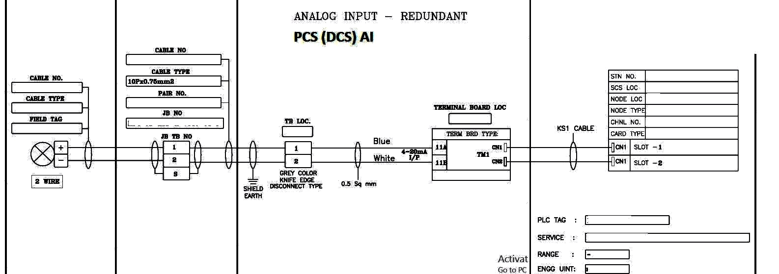
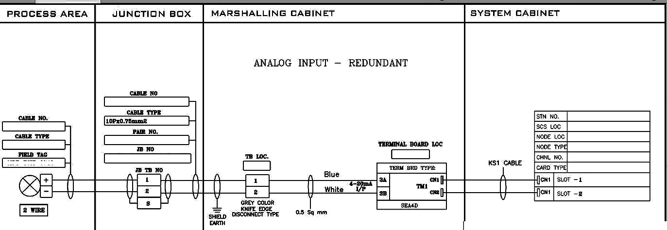
1)PCS LOOP AI (ANALOG INPUT)
Characteristics of loop
a)Primary cable (cable laid from marshalling cabinet to JB) will be of 20 pair X 0.75 sqmm. And secondary cable (cable laid from JB to field) will be 1pair X 0.75 sqmm. shielded cables
b)There will not be any 24V power supply in general case {240V flow transmitters are exceptions}, the 4 to 20mA is fed from control room AI cards
c)The card will be for the purpose of control monitoring type like (Yokogawa Centum CS/ Centum VP, Siemens SimaticPCS7 Emerson delta V,ABB System800xA,Honeywell ST3000 and Experion PKS, GE OC4000,Rockwell PlantPAx, Invensys Foxboro IA series)
d)This loop will provide the present parameters of the system like current level, pressure, temperature, flow etc in terms of mA
e)The fuse used in the TB will be of the type Grey colour knife edge disconnect type fuse.
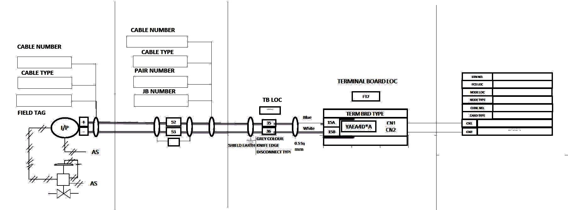
2)PCS LOOP(AO) ANALOG OUTPUT:
Characteristics of loop
a)Primary cable (cable laid from marshalling cabinet to JB) will be of 20 pair X 0.75 sqmm. And secondary cable (cable laid from JB to field) will be 1pairX0.75 sqmm. Shielded cables
b)There will not be any 24V power supply in general case {240V flow transmitters are exceptions}, the 4 to 20mA is fed from control room AO cards
c)The card will be of purpose of control/monitoring type like (Yokogawa Centum CS/ Centum VP, Siemens SimaticPCS7 Emerson delta V,ABB System800xA,Honeywell ST3000 and Experion PKS, GE OC4000,Rockwell PlantPAx, Invensys Foxboro IA series)
d)This loop will provide the command signal for controlling of the system like current level, pressure, temperature, flow control valves in terms of mA
e. The fuse used in the TB will be of the type Grey colour knife edge disconnect type fuse.
3. PCS/DCS LOOP DIGITAL INPUT(DI)
Characteristics of loop
a)Primary cable (cable laid from marshalling cabinet to JB) will be of 20 Core X 2.5 sqmm. And secondary cable (cable laid from JB to field) will be 2Core X 2.5 sqmm. shielded cables
b)There will be two 24V power supplies in general case, one for normally open condition status and another for normally closed condition status
c)The card will be of purpose of control/monitoring type like (Yokogawa Centum CS/ Centum VP, Siemens SimaticPCS7 Emerson delta V,ABB System800xA,Honeywell ST3000 and Experion PKS, GE OC4000,Rockwell PlantPAx, Invensys Foxboro IA series)
d)The fuse used in the feed through TB will be of the type Grey colour fuse TB with LED disconnect type fuse of value 50mA for the loop and two separate fuses of 1A for terminal board 24 volt DC power supply bus bar
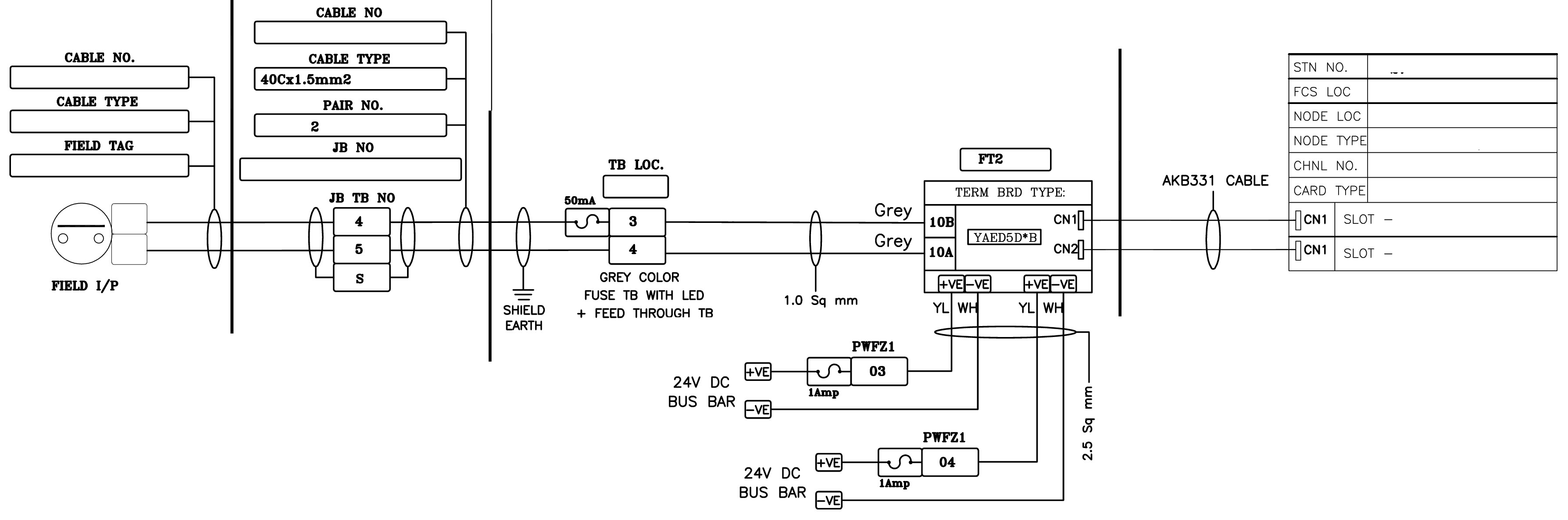
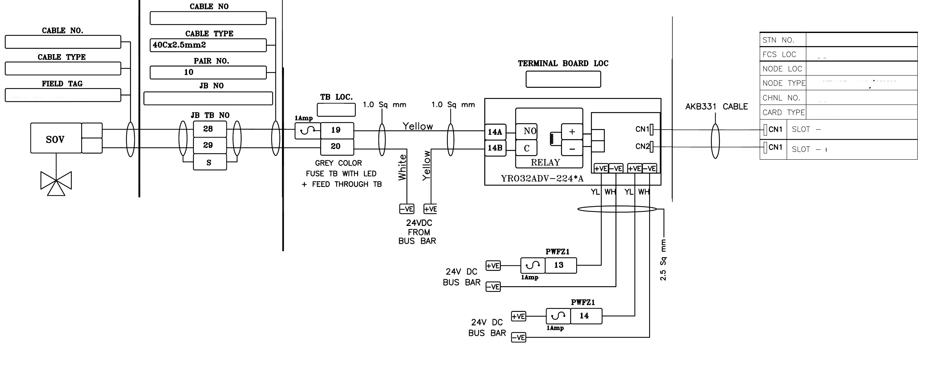
4) PCS/DCS LOOP DIGITAL OUTPUT (DO):
Characteristics of loop
a)Primary cable (cable laid from marshalling cabinet to JB) will be of 20 Core X 2.5 sqmm. And secondary cable (cable laid from JB to field) will be 2Core X 2.5 sqmm. shielded cables
b)There will be two 24V power supplies in general case, one for open command and another for closed command for ON/OFF valve SOVs along with relay and another 24 V in the loop between TB and relay (thus total three 24V supply.)
c)The card will be of purpose of control/monitoring type like (Yokogawa Centum CS/ Centum VP, Siemens SimaticPCS7 Emerson delta V,ABB System800xA,Honeywell ST3000 and Experion PKS, GE OC4000,Rockwell PlantPAx, Invensys Foxboro IA series)
d)The fuse used in the feed through TB will be of the type Grey colour fuse TB with LED disconnect type fuse of value 1A for the loop and two separate fuses of 2A for terminal board 24 volt DC power supply bus bar
B)ESD LOOP:
1)ESD DIGITAL OUTPUT (DO) LOOP:
a)Primary cable (cable laid from marshalling cabinet to JB) will be of 20 Core X 2.5 sqmm. And secondary cable (cable laid from JB to field) will be 2Core X 2.5 sqmm. shielded cables
b)There will be one(not 2 as in case of DCS DO) 24V power supplies in general case, for open/close command for ON/OFF valve SOVs along with relay and another 24 V in the loop between TB and relay
c)The card will be of purpose of emergency shutdown type (Yokogawa Prosafe RS, Invensys triconex,Honeywell Fail safe controller as a part of Experion/TPS,siemens S7-400F,Emerson deltaV SMART SIS,ABB 800xA High Integrty SIS)
d)The fuse used in the feed through TB will be of the type Grey colour fuse TB with LED disconnect type fuse of value 1A for the loop and one fuse of 2A for terminal board 24 volt DC power supply bus bar

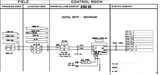
2)ESD DIGITAL INPUT (DI) LOOP :
a)Primary cable (cable laid from marshalling cabinet to JB) will be of 20 Core X 1.5 sqmm. And secondary cable (cable laid from JB to field) will be 2Core X 1.5 sqmm. shielded cables
b)There will be one 24V power supplies (not 2 as in case of DCS DO) in general case, for open condition /closed condition.
c)The card will be of purpose of control/monitoring type like (Yokogawa Prosafe RS, Invensys triconex,Honeywell Fail safe controller as a part of Experion/TPS,siemens S7-400F,Emerson deltaV SMART SIS,ABB 800xA High Integrty SIS)
d)The fuse used in the feed through TB will be of the type Grey colour fuse TB with LED disconnect type fuse of value 50mA for the loop and one fuse of 2A for terminal board 24 volt DC power supply bus bar
3)ESD ANALOG INPUT (AI):
Characteristics of loop
a)Primary cable (cable laid from marshalling cabinet to JB) will be of 20 pair X 0.75 sqmm. And secondary cable (cable laid from JB to field) will be 1pair X 0.75 sqmm. shielded cables
b)There will not be any 24V power supply in general case {240V flow transmitters are exceptions}, the 4 to 20mA is fed from control room AI cards
c)The card will be for the purpose of control monitoring type like (Yokogawa Prosafe RS, Invensys triconex,Honeywell Fail safe controller as a part of Experion/TPS,siemens S7-400F,Emerson deltaV SMART SIS,ABB 800xA High Integrty SIS)
d)This loop will provide the shutdown parameters of the system like current level, pressure, temperature, flow etc in terms of mA
e)The fuse used in the TB will be of the type Grey colour knife edge disconnect type fuse. Now a days, we use fuse along with knife edge for double protection
C) FGS/FNG LOOP:
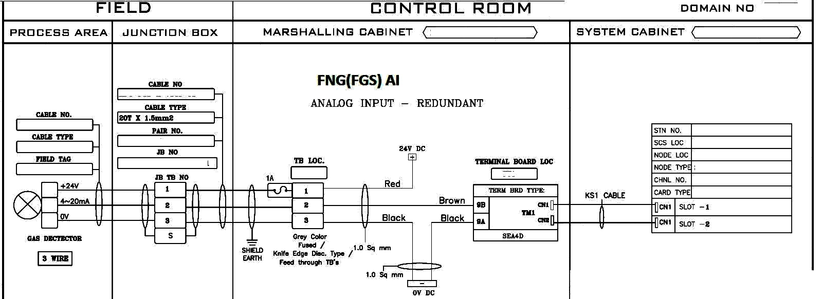
1)FNG ANALOG INPUT(AI) LOOP:
Characteristics of loop
a)Primary cable (cable laid from marshalling cabinet to JB) will be of 20 Triad X 1.5 sqmm. And secondary cable (cable laid from JB to field) will be 1Triad X1.5 sqmm. Shielded cables
b)There will be one 24V power supply and one 0 volt supply in general case, the 24 volt is fed for the first cable of the triad and 0 volt is fed to last cable of the triad
c)The card will be for the purpose of control monitoring type like (Yokogawa Prosafe RS, Invensys triconex,Siemens S7-400FH,Honeywell HS81-HSController,Emerson DeltaV SIS system)
d)This loop will provide the controlling/monitoring parameters of the system like gas LEL, flame quotient etc in terms of mA
e)The fuse used in the TB will be of the type Grey colour knife edge disconnect type fuse for 24 volt loop and knife edge for mA loop
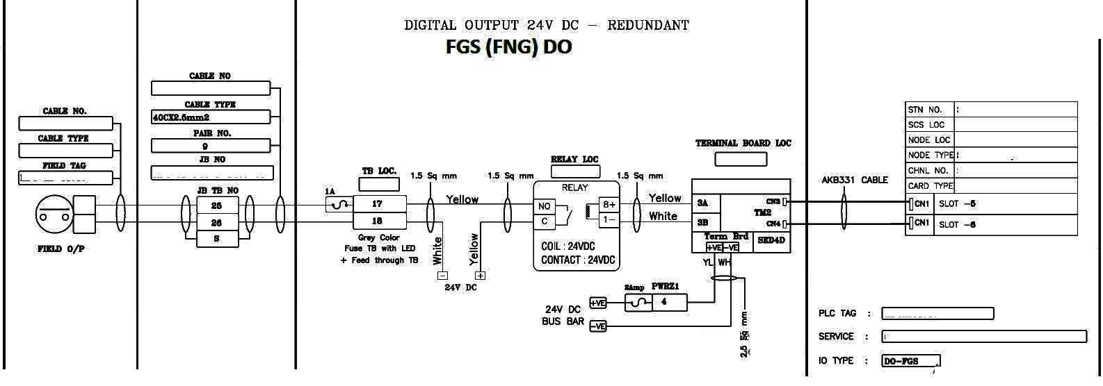
2)FNG DIGITAL OUTPUT (DO) LOOP :
a)Primary cable (cable laid from marshalling cabinet to JB) will be of 40 Core X 2.5/1.5 sqmm. And secondary cable (cable laid from JB to field) will be 2Core X 2.5/1.0 sqmm. shielded cables
b)There will be one(not 2 as in case of DCS DO) 24V power supplies in general case, for open/close command for ON/OFF valve SOVs along with relay
c)The card will be of purpose of emergency shutdown type (Yokogawa Prosafe RS, Invensys triconex,Siemens S7-400FH,Honeywell HS81-HSController,Emerson DeltaV SIS system)
d)The fuse used in the feed through TB will be of the type Grey colour fuse TB with LED disconnect type fuse of value 1A for the loop and one fuse of 2A for terminal board 24 volt DC power supply bus bar
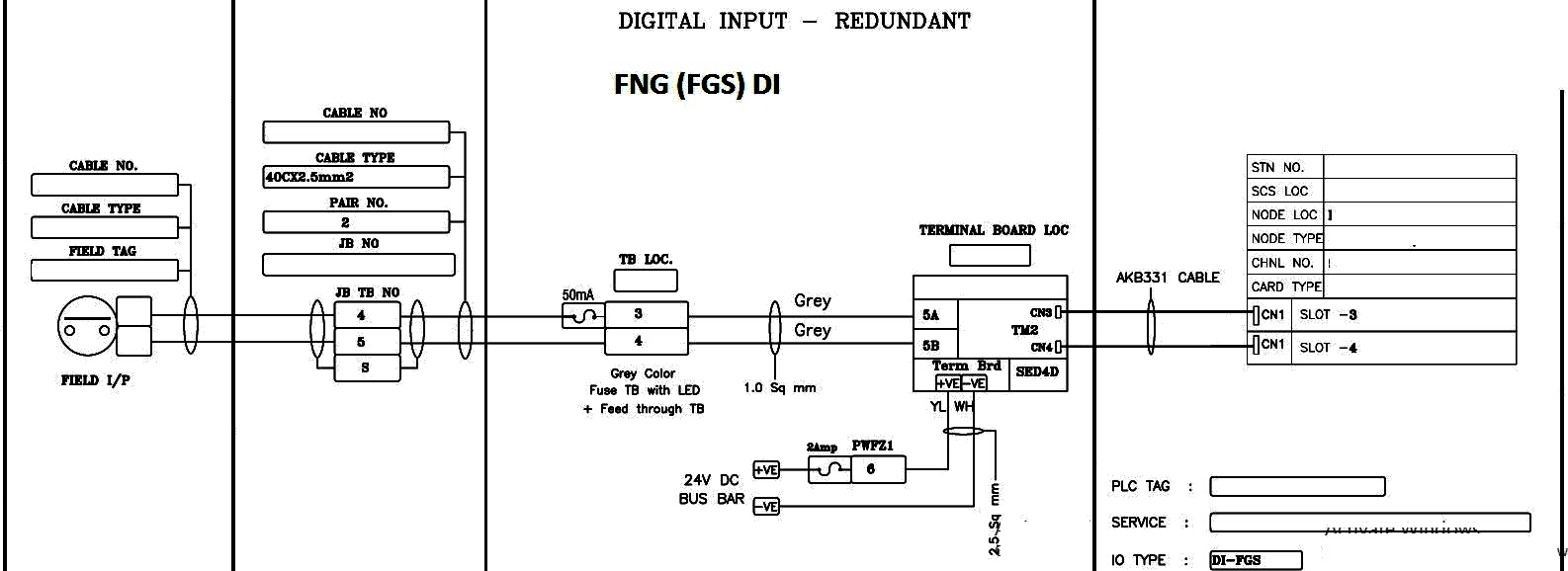
3)FNG DIGITAL INPUT (DI):
a)Primary cable (cable laid from marshalling cabinet to JB) will be of 20 Core X 2.5 sqmm. And secondary cable (cable laid from JB to field) will be 2Core X 2.5 sqmm. shielded cables
b)There will be one 24V power supplies (not 2 as in case of DCS DO) in general case, for open condition /closed condition.
c)The card will be of purpose of control/monitoring type like (Yokogawa Prosafe RS, Invensys triconex,Siemens S7-400FH,Honeywell HS81-HSController,Emerson DeltaV SIS system)
- d)The fuse used in the feed through TB will be of the type Grey colour fuse TB with LED disconnect type fuse of value 50mA for the loop and one fuse of 2A for terminal board 24 volt DC power supply bus bar
-
NB:
-
Generally AI/AO uses paired cable, knife edge fuse and no power supply.
-
DI/DO uses core cable, fuse TB with LED and 24 V supply in the loop with (or without) relay
-
DO/DI loop is assisted with minimum two 24 V power supply (one–24 V for ESD DI/FGS DI; two — 24V for ESD DO/ PCS DI / FGS DO and three — 24V for PCS DO-wet contact)
-
FNG uses triad cable for AI FGS with a combination of knife edge and fused TB with LED having both 4-20mA loop and a 24 V loop
-
DI fuses will be generally of the rating 50 to 100 mA while that of DO will be of 1A
-
DO will be always having a relay
-
Card for PCS/DCS will in most cases-Yokogawa Centum CS/ Centum VP, Siemens SimaticPCS7 Emerson delta V,ABB System800xA,Honeywell ST3000 and Experion PKS, GE OC4000,Rockwell PlantPAx, Invensys Foxboro IA series;
ESD -Yokogawa Prosafe RS, Invensys triconex;
FNG will be Yokogawa Prosafe RS, Invensys triconex;
RTU will be Yokogawa stardom
Source : kishorekoduvayur