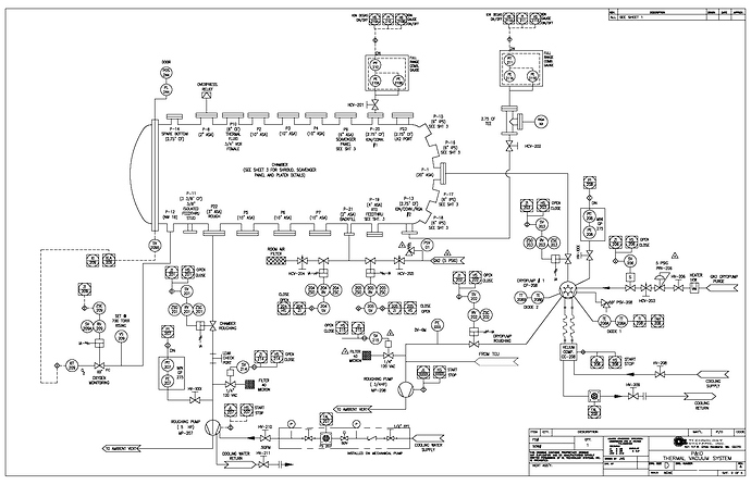
First time I heard about P&ID in my work place, my mind spontaneously thought about Proportional, Integral, and Derivative approach that I have learned before when I was in college. But, I was totally wrong, P&ID here is stand for Piping and Instrumentation Diagram .
Other useful documents other than P&ID’s or sometimes clients or other contractors may call these EFD’s (Engineering Flow Diagrams), MFD’s (Mechanical Flow Diagrams), or UFD’s (Utility Flow Diagrams).
Actually, P&ID is the “roadmap” to show the path to the piping and the destination for the instrument signals and highways. It shows the path to where the instruments connect to the process, i.e. piping, vessels or equipment, and how the equipment is being monitored or controlled. It is the communications link for all disciplines (Process, Piping, Instrumentation/systems, electrical, and the mechanical equipment groups).
In other words, P&ID could be said like the “Bible”, as the highest level of authority for control systems. It is the master plan for instruments and control systems for the project. For example, if there is a discrepancy between several documents, the P&ID is usually regarded as the highest authority; therefore the P&ID must be kept current as much as possible.
P&ID’s show diagrammatically all the equipment for the process; all the piping with sized lines, major and minor, including block valves and other devices; instrumentation and controls, including in-line and off-line devices. They also show the utility systems for the plant.
It is developed from the Process Flow Diagrams (PFD’s). The mechanical and hydraulic design portions of the P&ID’s are the responsibility of Systems Engineering, but Instrumentation and control design is the responsibility of Control Systems Engineering (CSE).
Piping and Instrumentation Diagram
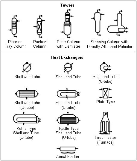
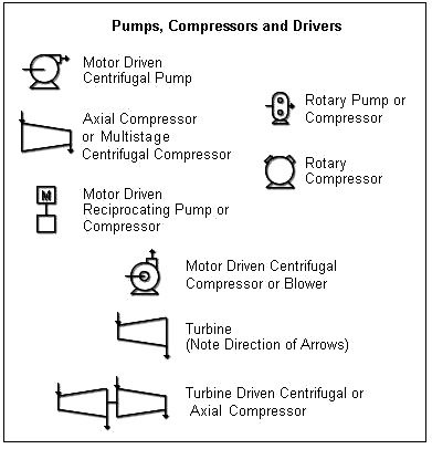
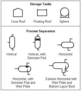
On the P&ID’s we can find schematic representation of all process equipment, like towers, drums, heat exchangers, heaters, pumps, compressors, drivers, etc. with their equipment tag numbers. Just like the instrumentation, the representation for some of the mechanical equipment such as compressors may be of the simplified representation. Sometimes the vendors P&ID’s may be used for the detailed version.
All interconnecting process and utility piping with sizes, line numbers, pipe classes, and service (fluid) codes also could be found on P&ID’s. The P&ID’s then used to determine the service for the index.
Besides all that I mentioned above, P&ID’s also show Block and check valves, piping components (traps, strainers, ect.), SP items, pressure relief devices, ect. Piping spec changes is also shown on P&ID’s since this is an important issue which means that the pipe has changed classes (I.e Class 300 to Class 150, or maybe C.S. to alloy.
Another thing we would find here is boundaries around supplier packages, but this may be later in the project when vendor documentation is received. This is also important because there can be issued such as input and output signals that go from package equipment vendor furnished instruments to the DCS or SIS.
These instruments which are furnished by the package equipment vendor should not be requisitioned again. Also there could be issued and designated such as instruments furnished by the package equipment vendor, but shipped loose and mounted in piping external to the package.
Tie-ins and breaks between new and existing piping, equipment, and instruments just like an existing transmitter that has a new signal run into the control room, or furnishing a new orifice plate into existing orifice flanges, and could be existing TW’s that we put new thermocouples or RTD’s into are also shown on the P&ID’s.
Just like its name, Piping and Instrumentation Diagram, this drawing also show the Instrumentation and controls such as control room “bubbles” including DCS, SIS, and PLC devices. Usually an L (Low), LL (Low Low), H (High), or HH (High High) located outside and adjacent to the DCS bubble indicated a DCS alarm. But for revamp project on existing P&ID’s, we may see the alarms shown in DCS bubbles, i.e. PAH, LALL, etc.
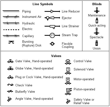
The P&ID’s should show the field instruments including panel-mounted devices, analyzers, flow elements, and control valves. This includes diagrammatically depicting instrument wiring, pneumatic signals, data links, capillary tubing, and logic interlocks.
It also shows instruments that are steam or electrically heat traced, location of field devices on panels, instrument air to solenoid valves for on-off valves, and even notes to describe special requirements about the instruments.
Last but not least, the P&ID’s should also show typical details for instruments whose connections and impulse lines require flushing to prevent plugging from solid particles in the fluid, and also a list of Tag Nos. requiring this detail. And finally this detail should show any check valves, small restriction orifices, purge meters, etc. that are required.
Credits: Sandra Eka Ristianjani
